#40 MMT/National Standard Taper: Equivalent to NMTB 40 ?

Collapse
X
 
  • Filter
  • Time
  • Show
Clear All
new posts
  • EddyCurr
    Senior Member
    • May 2009
    • 3471

    #40 MMT/National Standard Taper: Equivalent to NMTB 40 ?

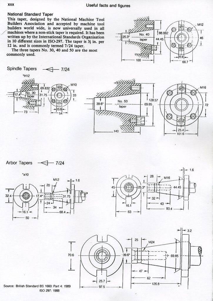
    Are current end/shell mill holders designated as NMTB 40 (5/8-11 drawbar)
    suitable replacements for manual machines with quills originally configured
    for #40 MMT/National Standard taper holders?

    .
  • rklopp
    Senior Member
    • Feb 2003
    • 582

    #2
    Yes, indeed that is the case. (Had to stretch Y-E-S to reach the 10-character minimum.)

    Comment

    • EddyCurr
      Senior Member
      • May 2009
      • 3471

      #3
      Thank you.

      .

      Comment

      • oldtiffie
        Member
        • Nov 1999
        • 3963

        #4
        Same

        The NMTB and ISO tapers are exactly the same except that the ISO/DIN/Metric versions use M (metric/UNC) thread series draw-bars.

        The ISO measurements/dimensions are exact "hard conversions" of inch to mm.

        The ISO adopted the USA NMTB as a DIN standard - entirely.

        Comment

        • EddyCurr
          Senior Member
          • May 2009
          • 3471

          #5
          Originally posted by oldtiffie
          The NMTB and ISO tapers are exactly the same except that the
          ISO/DIN/Metric versions use M (metric/UNC) thread series draw-bars.

          The ISO measurements/dimensions are exact "hard conversions" of inch to mm.

          The ISO adopted the USA NMTB as a DIN standard - entirely.
          So if I happen to stumble upon a supply of ISO-40 end or shell mill holders,
          then these too can be used in a vintage north american machine, with
          the proviso that a drawbar with a suitable metric threaded end (M16 ?)
          will be required ?

          Thank you for the explanation and illustration.

          .

          Comment

          • whitis
            Senior Member
            • Aug 2009
            • 702

            #6
            Yes. But more importantly, CAT-40/BT-40/etc. are basically the same except the pilot at the rear end is missing and replaced with a removable pull stud. Apparently the same 5/8-11 thread (different on metric versions) but it starts a little closer to the spindle nose so you may need to adjust drawbar length. Actually, the NMTB-40 has a 5/8-11 and a 1/2-13 thread on the drawbar but 5/8-11 threads on the tool holder. The 1/2-13 part is supposed to be 1.25" long (at least 1" usable thread) while the minimum depth of the 5/8-11 threaded hole on the CAT-40 tooling is only guaranteed to be 1.12" minimum. The 1/2-13 part is likely to get in the way so a new drawbar will probably be needed but that is the only change likely to be needed, other than removing any pull studs (usually sold separately since there are multiple incompatible styles) from the tooling.

            If I had a machine with a NMTB-40 spindle, I would be putting CAT-40 tooling in it, not the outdated NMTB-40 style with the pilot. You can't use the NMTB style in a machine with an automatic tool changer (well, you probably can if you remove the ATC, drawbar, and fingers, since the bore for the pilot is there but used for the fingers). Then later I would upgrade the drawbar power drawbar with gripper fingers for the pull stud. It has been suggested long ago on this forum that the threads on CAT-40 are designed to be more or less permanently assembled with a pull stud rather than constant drawbar insertion/removal so they might not be as wear resistant, but I don't put much stock in that. NMTB-40 had a minimum of 1.12" of usable 5/8-11 thread on the draw bar and the CAT-40 tooling has a minimum of 1.12" of usable 5/8-11 thread on the tool holders.

            You will find drawings of both in the Machinery's Handbook, though the CAT-40 is in the CNC section. Metric versions in the Machine Tool Design Handbook. NMTB only in the 1950 American Machinist's handbook. Plus I have a copy of ANSI B5.18-1972 which is the standard form NMTB. B5.47-1972 deals with the horizontal mill arbor variation of NMTB-40.

            CAT-40 tooling can be migrated through a machine upgrade (CNC machining center) or shared with CNC machines. NMTB can't. If you will never have CAT-40 machines, NMTB-40 tooling, however, is available cheap USED (because nobody with modern machines wants it). New, CAT-40 tooling is likely to be more readily available, though NMTB-40 tooling is available. Import CAT-40 collet chucks can be had pretty cheaply, not so the NMTB-40, though import end mill holders are about the same price.

            Comment

            • oldtiffie
              Member
              • Nov 1999
              • 3963

              #7
              Not so sure

              Originally Posted by oldtiffie
              The NMTB and ISO tapers are exactly the same except that the
              ISO/DIN/Metric versions use M (metric/UNC) thread series draw-bars.

              The ISO measurements/dimensions are exact "hard conversions" of inch to mm.

              The ISO adopted the USA NMTB as a DIN standard - entirely.
              Originally posted by EddyCurr
              So if I happen to stumble upon a supply of ISO-40 end or shell mill holders,
              then these too can be used in a vintage north american machine, with
              the proviso that a drawbar with a suitable metric threaded end (M16 ?)
              will be required ?

              Thank you for the explanation and illustration.

              .
              Not so sure about that Eddy.

              You would need to check the driver/key, shell-mill spigot and retaining screw details as I'd be surprised if old ISO/DIN holder details for any shell-mill, end-mill or adaptors complied with US/inch details as I'd expect all ISO/DIN shell-mill etc. details to be metric.

              Only the NMTB series as per my pic apply as regards the standards and inter-changeability.

              Comment

              • macona
                Senior Member
                • Aug 2006
                • 9425

                #8
                Other difference between BT and CAT is the V groove for the tool changer.

                I use BT-30 on my mill with a draw bar.

                Comment

                • oldtiffie
                  Member
                  • Nov 1999
                  • 3963

                  #9
                  Good points

                  Good points macona.

                  Like these?:

                  Become a Machineryhouse Mate! Australia's leading supplier of Engineering, Metal & Wood working machinery. Buy online or in-store.


                  Become a Machineryhouse Mate! Australia's leading supplier of Engineering, Metal & Wood working machinery. Buy online or in-store.


                  and:
                  Become a Machineryhouse Mate! Australia's leading supplier of Engineering, Metal & Wood working machinery. Buy online or in-store.


                  Become a Machineryhouse Mate! Australia's leading supplier of Engineering, Metal & Wood working machinery. Buy online or in-store.

                  Comment

                  • MuellerNick

                    #10
                    Other difference between BT and CAT is the V groove for the tool changer.
                    The V-groove for the tool changer wouldn't hurt. It are the two slots milled in. One of them is to narrow to accept its counterpart on the spindle.


                    Nick

                    Comment

                    • macona
                      Senior Member
                      • Aug 2006
                      • 9425

                      #11
                      Another thing you need to watch out for there is a specific orientation with the drive dogs on the spindle. One is closer to the center line of the spindle. The tool holder will still fit in but it will have considerable run out as it is not fully seated in the taper.

                      If you do have a machine with a drawbar that uses pull studs it seems to be that the BT spindles use a different geometry on the pull stud than the cat spindles. There are adapter pull studs to put a BT tool in a CAT spindle and vice-versa. I sold a BT-40 Nikken spindle speed to my friend who has a Milltronics VMC with a CAT spindle. He was able to get one of these adapters to make it work.

                      Comment

                      • willmac
                        Senior Member
                        • Mar 2007
                        • 729

                        #12
                        I think that the only way you can reasonably use CAT40 tooling in an ISO 40/NMTB 40 spindle is to remove one of the drive keys. This is a bodge and I wouldn't recommend it. Perhaps you could make some special drive keys, but this is probably an even worse bodge.

                        You may however be able to use BT40 tooling, although I have never tried this. BT40 has symmetrical drive keys.

                        It is preferable to choose one tooling standard for a machine and stick to it. Constantly changing drawbars is a pain. I didn't follow this advice and I have quite a collection of drawbars X2 because I have a horizontal/vertical spindle mill.
                        Bill

                        Comment

                        • carlquib
                          Senior Member
                          • Dec 2001
                          • 386

                          #13
                          Hey willmac, you can either kludge it like you mentioned, works and unless you are turning a tool that will use a lot of HP you won't have a problem with just one key. My mill has a 7 hp motor and I haven't buggarred it yet, even using a 1 1/4" endmill taking a serious cut or using the 3" shell mill. One is still probably better than an R8 tool holder. I have a modified key in my mill so both keys are driving the Cat tooling. It is a pain to change the key back and forth but I have it in the vertical head and leave the horizontal with the symmetrical keys because I rarely put cat tooling in the horizontal spindle. I too have acquired quite a collection of draw bars. I make all of mine out of grade 8 5/8-11 allthread. I cut them a little longer than I need then weld a nut on the end, I then thread a second nut onto the rod. Using this setup I can screw the rod into the toolholder with just finger pressure and then use the second nut to pull the toolholder into the spindle. I am hoping that this method will spare wear on the toolholder threads since there is no motion of the threads under pressure.
                          -brian

                          Hello, my name is brian and I'm a toolaholic.

                          Comment

                          • EddyCurr
                            Senior Member
                            • May 2009
                            • 3471

                            #14
                            The replies have been very helpful.

                            The opportunity to substitute a CAT40 taper was promising, alas there
                            turned out to be a catch - albeit a surmountable one. However, for now
                            sticking with NMTB seems a conservative & frugal place to begin the
                            tooling process.

                            For someone who already has a modest investment in R8 tooling, a
                            reducing adapter (NMTB 40 to R8) seems to be a sensible first purchase.
                            Perhaps this adapter, together with a shell mill holder for some 4" mills on
                            hand will carry the effort until needs/wants are better established.

                            .

                            Comment

                            • whitis
                              Senior Member
                              • Aug 2009
                              • 702

                              #15
                              Originally posted by willmac
                              I think that the only way you can reasonably use CAT40 tooling in an ISO 40/NMTB 40 spindle is to remove one of the drive keys. This is a bodge and I wouldn't recommend it. Perhaps you could make some special drive keys, but this is probably an even worse bodge.
                              You take out one or both drive keys, cut a little off the inside edge and replace them. This isn't a bodge, it is apparently how sensibly designed machines ship from the factory.

                              ANSI B50-1985, according to machinery's handbook, which apparently corresponds to CAT-40, specifies the key slots are a different depth measured radially from the centerline: One starts 0.985" from the center line and the other 0.890".

                              Some CAT-40 spindles come asymmetric and require the tool holder to be inserted a certain way in the changer. If it isn't bad things can happen like messing up your spindle taper or the tool holder sitting crooked. Other CAT-40 spindles come symmetric.

                              ANSI B5.18-1972 (NMTB-40) specifies that the key on the spindle nose itself starts 0.904 to 0.910" from the center line and that the slot on the tool holder starts 0.875 to 0.890".

                              The various v-flange standards have some minor differences in the flange dimensions. The diameter and thickness of the flange differ. Further the dimension of the cylindrical body for a certain length below the flange is standardized to different values. ANSI specifies the same diameter as the taper at the gage line and the europeans enlarged it to 50mm. Where the ANSI/CAT key slots go all the way through the flange the BT40/ISO40 ones are blind with a radius in the keyway when viewed from the side, but this radius probably starts beyond the end of the ANSI/CAT keys, as the BT/ISO flange is thicker. DIN and IS (Indian Standard) keyways don't have the radius. JIS (Japan) is apparently the same or similar to the BT standard.
                              The vgrove in the flange is a different distance from the gage line.

                              There are subtle differences on the taper side as well, but the only one of consequence is the different pull stud thread.


                              With the proper keyway dimensions, a spindle designed for interoperabiity should be able to take either type of tooling (accounting for drawbar/pullstud thread differences) and a tool holder with suitably chosen dimensions for interoperability should fit in either spindle - though auto tool changers may be fussy about the flange/body/grove differences.

                              Different machines can require different pull studs, requiring you to swap out the pull studs when moving tooling from one machine to another until you replace the fingers on the machines to handle the same type of pull stud. Metric vs imperial threads for the pull stud probably won't amount to much difficulty since you can probably get the different pull studs in both threads.

                              Comment

                              Working...
                              X