Why was this lathe topslide designed like this?

Collapse
X
 
  • Filter
  • Time
  • Show
Clear All
new posts
  • S_J_H
    Senior Member
    • Mar 2006
    • 1182

    Why was this lathe topslide designed like this?

    I posted a similar thread at PM,

    I have a old Stark no3, The slide rest is not made by Stark it seems.
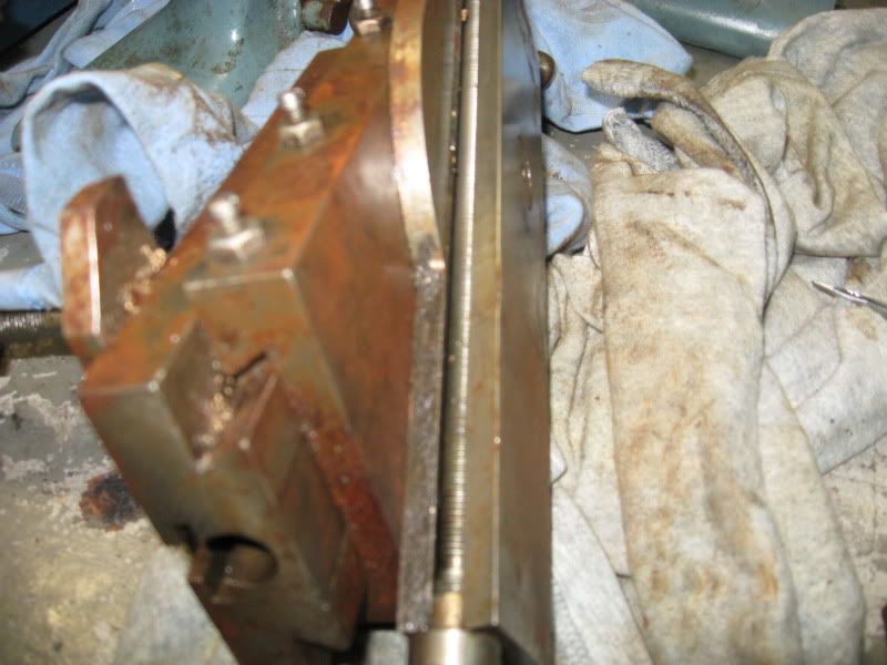
    But I do not understand why it was designed with a exposed leadscrew, and no flat surface for the dovetail other than on the degree radius on this side?
    At first I thought this slide had the dovetail flat broken off on the leadscrew side.
    But after more research I found several other topslides made like this.
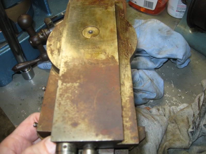
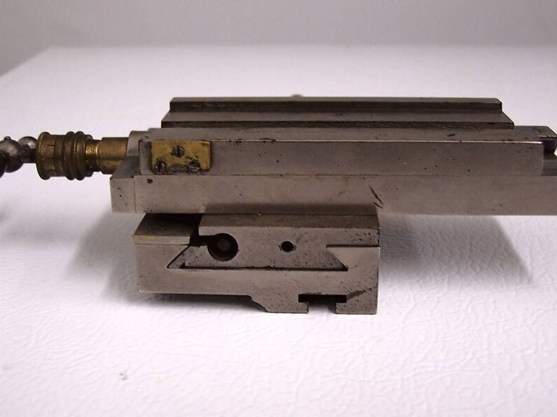
    This is what I have-
    The topslide with a exposed leadscrew and no flat part of the dovetail -


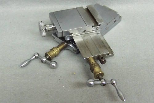
    And here is a Hardinge/Cataract topslide pic taken from http://www.lathes.co.uk/ showing the exact same design.


    And I found several other topslides with this design used on the old precision bench lathes.
    I don't get it and see no benefit, why did several lathe builders use this design?
    Steve
  • J Tiers
    Senior Member
    • Jan 2004
    • 44377

    #2
    The screw is underneath, protected, and the top of the slideway is solid.

    It's actually a nice design in many ways, even if a bit odd. The solid surface forms a good support for the slide, or anything else that might be mounted.

    Many of those older machines are much less prone to chatter than nominally similar machines (in size etc) of "newer" design. That slideway design is probably one reason.
    CNC machines only go through the motions.

    Ideas expressed may be mine, or from anyone else in the universe.
    Not responsible for clerical errors. Or those made by lay people either.
    Number formats and units may be chosen at random depending on what day it is.
    I reserve the right to use a number system with any integer base without prior notice.
    Generalizations are understood to be "often" true, but not true in every case.

    Comment

    • darryl
      Senior Member
      • Jan 2003
      • 14429

      #3
      Probably is more rigid, maybe longer range of motion from the compound, might even be more accurate. Probably a tighter and longer lived fit to the leadscrew as well.
      I seldom do anything within the scope of logical reason and calculated cost/benefit, etc- I'm following my passion-

      Comment

      • S_J_H
        Senior Member
        • Mar 2006
        • 1182

        #4
        Thanks, I see your points. I was just comparing the top slide to my SB9 compound slide and it looks quite a bit more robust then the SB.
        I'm wondering if the top wide surface between the dovetails on the compound act as a bearing surface for the tool slide. It still has faint scraping and flaking markings.
        The bed is pretty hefty as well for it's size. On each side of the bed for around 6" in length it is solid iron.
        Steve

        Comment

        • S_J_H
          Senior Member
          • Mar 2006
          • 1182

          #5
          Another example taken from ebay-

          Perhaps somehow this arrangement is also more accurate for whatever reasons.
          Steve

          Comment

          • winchman
            Senior Member
            • Aug 2003
            • 4030

            #6
            Looks like the design completely eliminates the need for a gib to control play in the dovetail. The setscrews on the halfnuts for the leadscrew also adjusts the play in the dovetail.
            Any products mentioned in my posts have been endorsed by their manufacturer.

            Comment

            • MuellerNick

              #7
              Very interesting design!
              As already noted, the leadscrew is quite well protected. In fact, better than with other designs. It's on the lee side from where the chips come flying in.
              The other advantage is, that it lacks the long slot for the nut to have access to the leadscrew. More rigid!
              Furthermore, as it looks, the whole top of the lower part is used as a way surface. Better damping, less wear, more rigid.
              Then we do have the slanted part of the dovetail (pointing away from the operator) that is not interfered with gibs etc. As this is the direction of the cutting force, a wanted feature. At the operator's side, where the gib is, you don't need that much way-surface, as the load is smaller.

              That's a rare, but very clever design!


              Nick

              Comment

              • Ian B
                Senior Member
                • Dec 2002
                • 2945

                #8
                Steve,

                Most modern lathes have the topslide the other way up, ie. with the short part bolted to the cross slide, and a longer travelling top part. This automatically means that the feeedscrew is hidden, but at full forward extension, the slide isn't too well supported.

                Older designs had what you have - a long fixed slide and a shorter travelling part. They all have the problem of an exposed feedscrew.

                I had a 3 1/4" Box-Ford like that. It had a long topslide, because the saddle only clamped to the bed. Instead of having the feedscrew in the side dovetail, there ws a strip of spring steel over the centrally-mounted fedscrew that passed through a slot in the nut.

                Different solutions to the same problem.

                Ian
                All of the gear, no idea...

                Comment

                • jackary
                  Senior Member
                  • Jun 2006
                  • 299

                  #9
                  Slightly OT but here is one i designed and made. I can be moved and rotated anywhere on the cross slide and locked in position with the lever on the side

                  Alan

                  Comment

                  • John Stevenson
                    Senior Member
                    • Mar 2001
                    • 16177

                    #10
                    Alan,
                    Any chance of shots from underneath in a new thread please ?
                    .

                    Sir John , Earl of Bligeport & Sudspumpwater. MBE [ Motor Bike Engineer ] Nottingham England.


                    Comment

                    • willmac
                      Senior Member
                      • Mar 2007
                      • 729

                      #11
                      Jackary-

                      That looks really good. Will it fit the ML7 cross-slide? If so I would really appreciate some more photos, details, or even better, drawings if you have them. I find the original ML7 design frustrating. The Radford design is intended for a Super7 otherwise I would have had a go at building that version.

                      Apologies to OP, this is a bit off topic. Reply in a new thread or by PM if you think that is better.
                      Bill

                      Comment

                      • S_J_H
                        Senior Member
                        • Mar 2006
                        • 1182

                        #12
                        Thanks for the comments, I do understand the benefits of this design. And it appears on my slide the upper flat between dovetails is indeed a bearing surface.

                        But none of this explains why there is no lower flat on the left side dovetail as shown in this pic of a watchmakers slide that is very much like mine-


                        A little wider topslide and the leadscrew could be fully enclosed and the topslide could have even more support. But they chose not to do that for some reason.

                        Steve

                        Comment

                        • S_J_H
                          Senior Member
                          • Mar 2006
                          • 1182

                          #13
                          lol!! It was right in front of me the entire time! It has to be made in this way for the leadscrew nut on the side. Otherwise it would need the upper open channel as used in a conventional type slide.

                          Ok where is my dunce cap..
                          Last edited by S_J_H; 10-30-2010, 12:07 PM.

                          Comment

                          • John Stevenson
                            Senior Member
                            • Mar 2001
                            • 16177

                            #14
                            To get the handle out of the way of the tailstock ?
                            .

                            Sir John , Earl of Bligeport & Sudspumpwater. MBE [ Motor Bike Engineer ] Nottingham England.


                            Comment

                            Working...
                            X