How do I measure this? (small round stuff with angles)

Collapse
X
 
  • Filter
  • Time
  • Show
Clear All
new posts
  • MrSyil
    Junior Member
    • Sep 2009
    • 8

    How do I measure this? (small round stuff with angles)

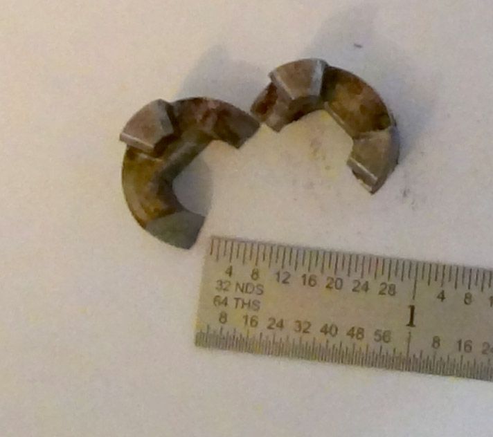
    A coupler in our icemaker broke and I'm not paying $60 for this tiny piece of metal. I have a small CNC mill so making the part is easy. Getting the dimensions is the hard part. Most of the projects that I've worked on had linear features that were relatively easy to measure with calipers. I've run into a few other parts with similar issues but this one is so simple that I thought this would be a good opportunity for me to learn the right way to dimension it. I have digital calipers, micrometer, surface plate and a height gage. I don't have any gage pins, radius gages or angle gages. Are there some techniques that I could use to get the dimensions that I need to draw this up in CAD?

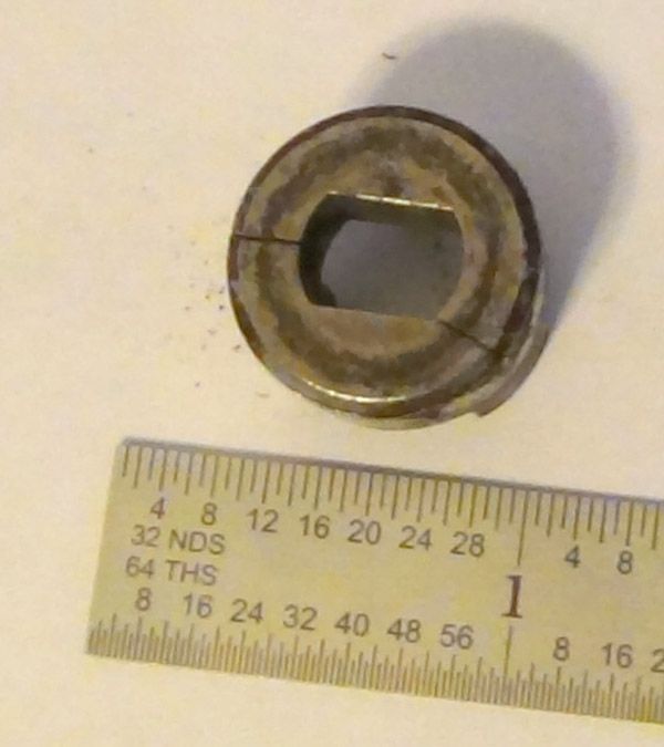
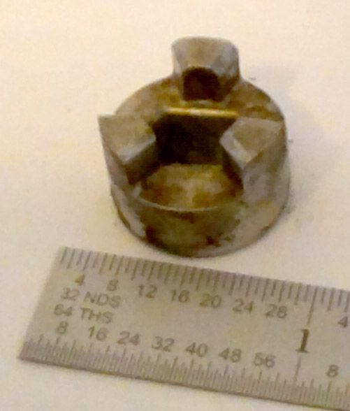
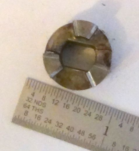
    The angle of the lugs and the radius on the through hole are the most difficult measurements for me.

    The coupler is 0.70" in diameter and 0.50" tall.


  • smalltime
    Senior Member
    • Nov 2009
    • 189

    #2
    First thing to do is super glue the thing together.

    Then start at it. If you have a cad program, it's going to be easy. Having the mating piece will also be a plus.

    The only dicey thing I see on it it the inside hole. That will need some handwork to fit the shaft.

    BTW, we have a store here in KC that is called MarBeck.

    Repair your favorite appliance with our selection of blender parts, coffeemaker parts, grill parts, washer and dryer parts, KitchenAid Mixer Parts and more!


    Just sayin'

    Comment

    • Bob Fisher
      Senior Member
      • Jan 2006
      • 1341

      #3
      I would not worry too much about the angles, they are there for release from the mold. I don't think there has to be a precision fit to the mating piece since it only drives in one direction. Don't over engineer it. Bob.

      Comment

      • RussZHC
        Senior Member
        • Mar 2010
        • 2411

        #4
        I'd like to take a "wild" guess...I don't have anything that you list either nor a surface plate, height gage. Could you not have a probe of some sort, like for a DTI, held in the spindle of the mill and just go
        "touch, touch" and get measurements that way?
        Also an opportunity, legitimate, to purchase more machining stuff . I am also not convinced some of those small radii are very specific, just square edges knocked down (?)

        Comment

        • goodscrap
          Senior Member
          • Apr 2012
          • 285

          #5
          for the angles you could take some close up pics with a digi camera on macro, make sure you're as square on as poss to the feature. print them out and draw lines on them so you can break out a protractor measure the angles, you can even scale some of the features from the print and measure the remnants of the original for comparison. to be fair i doubt most of it needs to be that accurate

          edit to add: the width of the dogs can be measured and then used to work out the angle of each dog, input the diameter and chord length into something like the calculator in the link below and that will give you the dog angle. the chamfers on the top you could probably file by hand if needed.

          have to assume the dogs are on a basic 120degree equal spacing, though you could measure the gaps between them in the same way (and input into calculator) to confirm once you've glued it back together


          chord calculator (scroll down to the input chart):

          Circle Sector calculator, Circle Segment Calculator, Arc Calculator, Circle Chord Calculator


          also the shaft fits on will give you the nominal diameter of the bore, and the flats look to be equal

          you can always print out the cad drawing 1:1 and overlay it to the real thing to see if it's in the right ball-park

          Cheers
          Brian
          Last edited by goodscrap; 11-19-2012, 05:48 PM.

          Comment

          • dave5605
            Senior Member
            • Apr 2008
            • 338

            #6
            Seems to me all you need is the caliper.
            You can measure everything except the actual angle of the 3 drive pins. Offhand it looks like the gaps between the pins is twice the width of the pin itself. Also it looks like all the angled sides converge on the centerline of the piece.

            Like someone else already mentioned, you probably have room for a fair amount of slop on the whole thing. No need to make it within .001" unless you want to.

            Besides with a CNC machine, if it comes out wrong, just tweak that dimension in the program and let it make another one. I could probably freehand it in an hour with some hand tools but that wouldn't be any fun. Hardest part would be making the hole for the shaft.

            Comment

            • HSS
              Senior Member
              • Feb 2008
              • 628

              #7
              That looks like a coupling from an old Scotsman flaker or IceOMatic flaker ice machine. Just be sure to account for the spider insert that goes between the driving lugs.

              Comment

              • MrSyil
                Junior Member
                • Sep 2009
                • 8

                #8
                Originally posted by HSS View Post
                That looks like a coupling from an old Scotsman flaker or IceOMatic flaker ice machine. Just be sure to account for the spider insert that goes between the driving lugs.
                Funny thing is that it doesn't have a spider and the repair manual doesn't show one either. The two couplers just drop together so it's easy to attach the ice bin.

                Comment

                • MrSyil
                  Junior Member
                  • Sep 2009
                  • 8

                  #9
                  I assumed that if you handed this part to a real machinist that there was a standard way, or two, to measure angles on a broken part.
                  What I probably do is take a macro picture, trace over all of the features in cad, dimension the angles and then average them.

                  Comment

                  • MrSyil
                    Junior Member
                    • Sep 2009
                    • 8

                    #10
                    Originally posted by dave5605 View Post
                    S
                    Besides with a CNC machine, if it comes out wrong, just tweak that dimension in the program and let it make another one.
                    yea, but the old one was chrome plated to resist corrosion so I'm going to make it out of stainless. Something that I usually avoid because I start breaking tools.

                    Comment

                    • danlb
                      Senior Member
                      • Nov 2008
                      • 7994

                      #11
                      I'm pretty sure that the standard ways are to use all the tools that you mention but that you do not have. An angle gage between any two legs will give the angle. A protractor will also work, of course. A bore gage will give you the radius for the inside of the center hole. A pin gage set inside the legs will give you that dimension.

                      Dan
                      At the end of the project, there is a profound difference between spare parts and left over parts.

                      Location: SF East Bay.

                      Comment

                      • lbhsbz
                        Senior Member
                        • Jan 2010
                        • 421

                        #12
                        Figure out the radius on the center hole by setting the piece down on a ruler and playing with a compass...keep walking the other end of the compass down the ruler until you get the same sweep...then read the number where the pointy end of the compass is sitting on the ruler.

                        If it were me, I'd just take a slice of aluminum round, drill 3 holes in it and press 3 pins through it. Machine a steel dummy shaft and sharpen it to press-punch the center hole accuratly after roughing it out close with round tools.

                        It's just an icemaker.

                        Now, if I was bored...I'd glue it back together, stick it in my rotary table chuck and spend about 5 minutes with an indicator in the quill figuring out my toolpaths, then machine it all...but I'm rarely bored anymore...I have a 2 year old kid.
                        Last edited by lbhsbz; 11-19-2012, 07:33 PM.

                        Comment

                        • chris4891
                          Junior Member
                          • Oct 2009
                          • 3

                          #13
                          Assuming you first glue the part back together, would the design of the mating components allow for you to just make a ring and press fit it over the OD to keep it in one piece?

                          Comment

                          • oldtiffie
                            Member
                            • Nov 1999
                            • 3963

                            #14


                            Hold it in a 3-jaw chuck on a rotary table set vertical. Use the hand-wheel graduations and a good dial indicator on a furface gauge - all on a good flat surface (ie mill table or surface plate).

                            Get one face/surface parallel to the base and measure the rest of the angles from there by rotating the rotary table until ach flat in turn is horizontal.

                            Then add or subtract each angle for each flat.

                            Comment

                            • Bob Fisher
                              Senior Member
                              • Jan 2006
                              • 1341

                              #15
                              I like Chris's idea ! Saves a lot of work if it can fit. Probably will not break again. Maybe ought to do both ends! Bob.

                              Comment

                              Working...
                              X