ac/dc resistance

Collapse
X
 
  • Filter
  • Time
  • Show
Clear All
new posts
  • dian
    Senior Member
    • Mar 2010
    • 3330

    ac/dc resistance

    recently i converted this tool to something usefull:


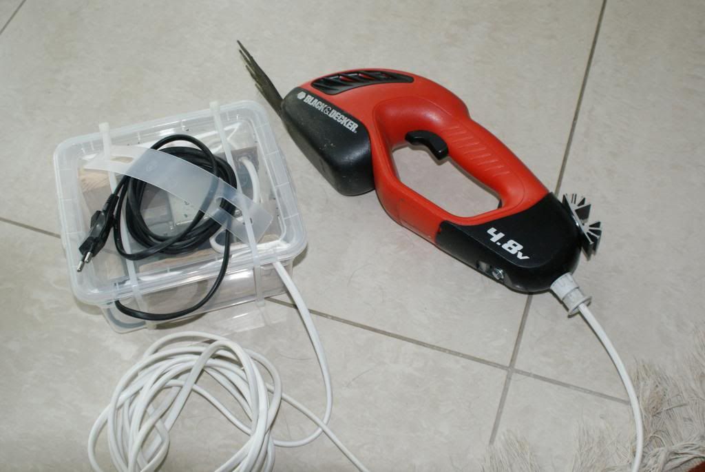
    its getting 8 volts from the transformer and now does its job.

    i took the trouble and installed the rectifier in the tool (i had a 16v capacitor in the handle, but it died a fast death, i dont know why, probably because it was 15 years old), as i didnt want to use a thick cable and my understanding was, ac loses less voltage than dc.

    but on second thought, is this really true and why?
  • The Artful Bodger
    Senior Member
    • Apr 2009
    • 8352

    #2
    Resistance is resistance and both AC and DC are effected by it but AC is also effected by 'reactance'.
    Ashburton, New Zealand

    Comment

    • Paul Alciatore
      Senior Member
      • May 2002
      • 17555

      #3
      Your losses, which are primarily due to heat from the resistance, will be almost exactly equal if the Voltages (RMS Voltage for the AC) and currents are the same.

      AC can have less loss in the wires IF you use transformers to convert it to a higher Voltage and then convert it back to the original Voltage at the other end. Since for a given amount of power that is carried by the wire, the product of Voltage and current is a constant but line losses are given by I^R, lower current equals less loss. It is not AC vs. DC that makes the difference, just the lower current when a higher Voltage is used. This trick is more useful with AC because it is a lot easier to change the Voltage level of an AC current than it is to do it with DC. This is why AC and high transmission Voltages are used by the power companies for long distance power transmission.

      But the transformers also have losses and you would be carrying them around and they have weight. I would just use a wire that is heavy enough for the current you have and live with it.
      Paul A.
      s
      Golden Triangle, SE Texas

      And if you look REAL close at an analog signal,
      You will find that it has discrete steps.

      Comment

      • MaxHeadRoom
        Senior Member
        • Apr 2010
        • 3389

        #4
        Originally posted by Paul Alciatore View Post
        . This is why AC and high transmission Voltages are used by the power companies for long distance power transmission.

        .
        Not in my province, we have 15 Hydro generating stations capable of 5485MW, the method now is to convert to DC for transmission and back to AC at the consumption end. Less losses claimed.
        Max.

        Comment

        • Lew Hartswick
          Senior Member
          • Aug 2002
          • 3674

          #5
          Originally posted by MaxHeadRoom View Post
          Not in my province, we have 15 Hydro generating stations capable of 5485MW, the method now is to convert to DC for transmission and back to AC at the consumption end. Less losses claimed.
          Max.
          Yes but at what voltage? It has been more "efficient" for a number of years now to use DC for long distance transmission. This has come about with the advent of switching components of adequate voltage rating.
          I don't know all the details but the long lines are in the 100KV range. The
          benefit comes about due to lessening the things like radiation losses.
          ...lew...

          Comment

          • ed_h
            Senior Member
            • Jan 2006
            • 997

            #6
            At 50/60 Hz, losses in the cable will be the same for AC and DC with the same current. Only at higher frequencies would there be significant difference.
            For just a little more, you can do it yourself!

            Comment

            • MaxHeadRoom
              Senior Member
              • Apr 2010
              • 3389

              #7
              Originally posted by ed_h View Post
              At 50/60 Hz, losses in the cable will be the same for AC and DC with the same current. .
              I assume they know what they are doing, they have been doing this for a considerable time, and they are just about to install a new transmission line at a cost of 3.28 Billion dollars, I have a couple of relatives who are engineers employed by the Hydro Co. I have been meaning for some time to get in depth details on this transmission method, so I will bring it up at the next B.Q.!!
              Max.

              Comment

              • ed_h
                Senior Member
                • Jan 2006
                • 997

                #8
                Max--

                I was actually responding to the OP.

                I do know that there is a tend toward HV DC transmission. I haven't researched it, but it may have something to do with not having to synchronize AC wave forms between and among plants. Also there is a small skin effect with AC that might ake a difference at very high voltages and currents. Though I've never worked on anything af this scale, long distance power transmission engineers may have to take reactances into account with AC.
                For just a little more, you can do it yourself!

                Comment

                • Lew Hartswick
                  Senior Member
                  • Aug 2002
                  • 3674

                  #9
                  Originally posted by ed_h View Post
                  At 50/60 Hz, losses in the cable will be the same for AC and DC with the same current. Only at higher frequencies would there be significant difference.
                  Not when the lines are quite long. This was the reason that in, either Norway
                  or Sweden, the LONG transmission lines were made DC back a Long time ago.
                  ...lew...
                  Perhaps the ones in Canada are not long enough to exhibit that loss.

                  Comment

                  • dp
                    Senior Member
                    • Mar 2005
                    • 12048

                    #10
                    The Pacific inter-tie between Washington state and California is a one-way DC wire. There are multiple wires for redundancy, but current flows only one way. The return is through the Earth. Both ends of the connection have huge grounding farms to carry the current into the Earth at low loss.

                    Comment

                    • ed_h
                      Senior Member
                      • Jan 2006
                      • 997

                      #11
                      Originally posted by Lew Hartswick View Post
                      Not when the lines are quite long.
                      Lew--The cable I was referring to was the one in the OP. I think you're right about long lines.
                      For just a little more, you can do it yourself!

                      Comment

                      • darryl
                        Senior Member
                        • Jan 2003
                        • 14430

                        #12
                        There's a couple of basics at work here- one is that battery operated tools use higher currents because of the lower voltage. When you have higher currents, there's higher losses in wiring and rectifiers. Secondly, any capacitors involved are subject to higher ripple current. Every pulse of current that goes into or out of a capacitor does its share of heating the series resistance of the capacitor. In a normal power supply, the filter cap gets its few big pulses as it initially charges up, then operates with lower ripple currents after that. If it's subject to constant cycling between peak voltage and something a lot lower, say half peak voltage, it's got a hard job to do. Switching caps are best for use like this- their main spec after voltage and capacity ratings are low series resistance, ESR. They are also usually rated for a higher temperature, 105 degrees vs 85 degrees.

                        Something to consider when developing a power supply for low voltage, high current applications is where to put the rectifier and capacitor. If you put them close to the transformer, there will be less resistance to the charge current and the peak voltage could come up faster and sustain longer. If you put them in the tool, with a length of wire between the transformer and the tool, you will lose average voltage at the tool. Also, with the cap and rectifier in the tool, the physical size of these components is limited. This will result in a lower current rating and higher voltage drop for the rectifier than might otherwise be the case, and it will definitely result in the capacitor having a capacity rating lower than would be desired.

                        Over the years, I've wired up several cordless tools, mostly drills, to separate power supplies. I've come to a few conclusions- first it's nice to have consistent performance from the tool, and you are not waiting for a battery which might be no good anymore to charge. Also, because you have a cord now, plus another device which must be plugged in, it's less convenient than a regular corded drill. Another point- assuming the power supply is up the task of supplying high currents with livable voltage drops, the wire you put between the supply and the tool needs to be fairly thick. By the time you have a thick enough gauge of wire, covered with insulation, it becomes much stiffer than you would otherwise like. More than once I've been on the search for a heavy gauge of wire that is flexible enough to live with.

                        A cordless tool running on 9 volts can easily draw 20 amps. It's not hard to lose 5 volts at 20 amps through a length of wire, so the performance of the tool can be weak, even if the unloaded rpm seems to be right up there where it seems it should be. And 20 amps is just a realistic figure for run of the mill cordless tools. I bet some these days can easily pull 50 amp surges- depending of course on what it's doing. Turning a small drill bit will be pretty easy, snipping twigs and brush or turning a hole saw will be demanding applications. It's hard to beat having the batteries right in the tool to supply high current through very short wiring.
                        I seldom do anything within the scope of logical reason and calculated cost/benefit, etc- I'm following my passion-

                        Comment

                        • Evan
                          Senior Member
                          • May 2003
                          • 41977

                          #13
                          The primary reason for using DC in transmission lines is that there is no need for rephasing capacitor banks every few hundred kilometres. Secondly, as mentioned, with the advent of very high powered and high voltage solid state switching systems the need to synchronize networks is eliminated. Skin effect isn't too much of an issue except at very high currents which require very large conductors, usually at sub stations.

                          Another major factor is corona loss. Ac inherently produces greater corona loss due to the changing polarity in respect of the space charge around the wires. If the wire voltage is constant in respect of the space charge it tends to suppress corona generation. If it alternates corona is enhanced because of the doubling of the voltage in respect to the space charge every half cycle.

                          The amount of power lost to corona can be severe, especially at high altitudes in poor weather. It can reach values in the >1 percent range per 100 kilometres. We have power lines in BC longer than 1000 kilometres. That includes the triple circuit 3 phase 545KV system a few klics down the road from me. It is that system that supplies the Pacific Intertie from the WAC Bennet Dam in Northern BC.

                          Here is an example of severe corona loss during seriously smoky conditions during a major forest fire.

                          Free software for calculating bolt circles and similar: Click Here

                          Comment

                          • Paul Alciatore
                            Senior Member
                            • May 2002
                            • 17555

                            #14
                            Jeeeeezz! I was only trying to illustrate a point. Yes, some power distribution is done with DC. But most is via AC and that was the primary consideration that lead early power companies to use AC and transformers. DC Voltage conversions were not that easy back then and even now, I suspect that other considerations (like avoiding the need for sync) may play a strong influence when DC is used.

                            My point was that the losses in a small scale system as the OP has are almost precisely the same with AC or DC if the Voltage and current is the same. And I did say "almost precisely" as I am sure someone will find some minor effect that proves that one or the other is slightly more efficient in a small system like this.
                            Last edited by Paul Alciatore; 05-03-2013, 01:40 AM.
                            Paul A.
                            s
                            Golden Triangle, SE Texas

                            And if you look REAL close at an analog signal,
                            You will find that it has discrete steps.

                            Comment

                            • dian
                              Senior Member
                              • Mar 2010
                              • 3330

                              #15
                              well, so i could have saved me some trouble.

                              Comment

                              Working...
                              X