Electrical Connection Help ???

Collapse
X
 
  • Filter
  • Time
  • Show
Clear All
new posts
  • JoeLee
    Senior Member
    • Aug 2009
    • 10873

    Electrical Connection Help ???

    I have just about completed another project that's been on the bench, one of my benches... for almost five years.
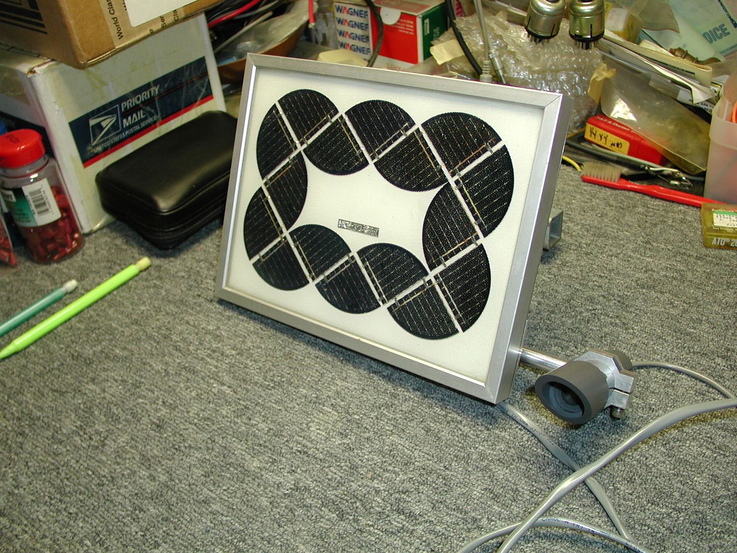
    This is a flasher circuit and solar cells.
    The machining part.............
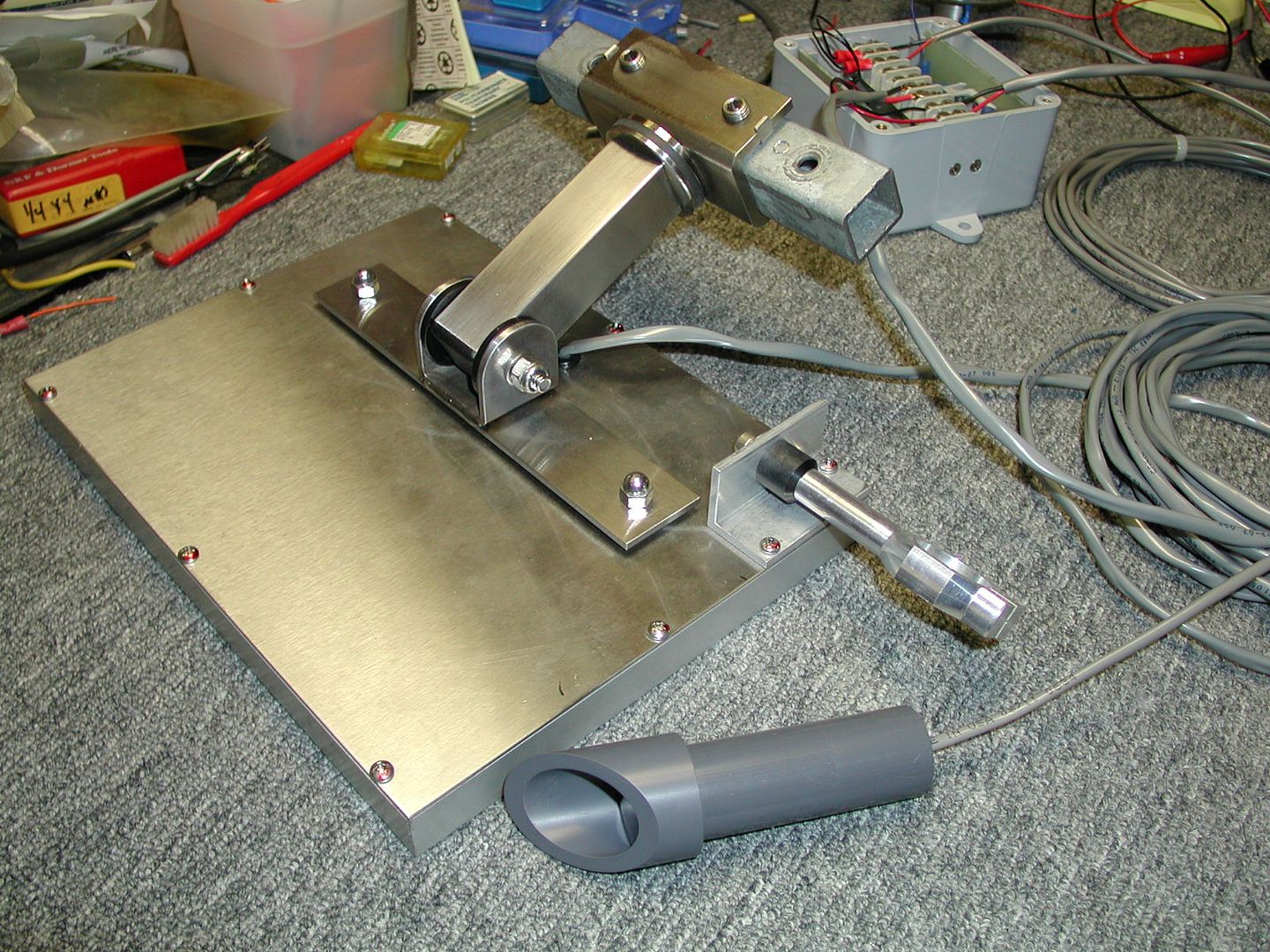
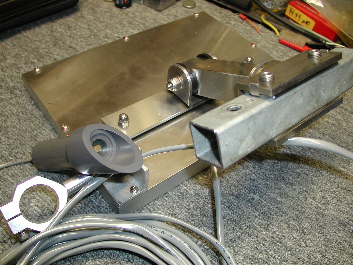
    I made the tilt / swivel / clamp mount out of stainless for the solar cells and also the PVC enclosure for the photo eye and the mount for it.
    This is going to clamp to a 1" square tube arm.
    The circuit consists of a small 6 volt flasher unit with a photo eye that came out of one of those barricade flashers.
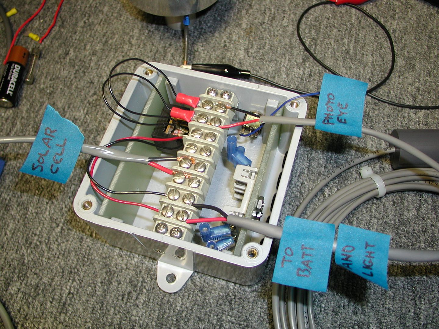
    I removed the photo eye and mounted it externally in the PVC enclosure that I made. The circuit board and associated parts are enclosed in the weather proof electrical box.


    Here is what I want to do.

    I want to bring in all the connections into the box, connect them to the terminal strip and then back out to what they have to connect to.
    What I want are some ideas on how to make the actual physical connections inside the box. I've included a sketch of what has to go into and come out of the box. The photo eye part is done, that was simple. What is left is the battery has to connect to the terminal strip, it should be fused and so should the light, there is a two fuse holder mounted in the box, I'm just not sure where in line to put it.
    I also have an on/off switch that needs to be placed in the circuit also. The light is in series with the negative terminal of the battery.
    The switch has to cut power to the light but not interrupt the charge to the battery. The sketch is in the next post.

    JL..................

  • JoeLee
    Senior Member
    • Aug 2009
    • 10873

    #2
    OK, here is a sketch of what connection go into and have to come out of the box...........can any one fill in the blanks????
    I just need some help on the actual physical connections inside the box.

    JL.................

    Last edited by JoeLee; 12-01-2015, 09:13 AM.

    Comment

    • Forestgnome
      Senior Member
      • Sep 2009
      • 1281

      #3
      I would put the fuse in series with the positive lead to the battery. Everything should be on the other side of the fuse away from the battery. Then make a branch on the negative lead of the battery, one going to the switch in series with the light, the other connected to the negative side of the solar cells. Nice work on the mount!

      Comment

      • Paul Alciatore
        Senior Member
        • May 2002
        • 17555

        #4
        I'm not really sure what you need. Do you need a schematic or wiring diagram for the box? Are you asking about wire types and sizes? Terminal types? Or what?

        One comment that I have is I see two insulated, crimp on terminals on the terminal strip. They appear to be poorly crimped. Did you use the proper crimping tool on them? There should be a "flat" on both sides of the insulation centered over the inner, metal barrel. And another "insulation" crimp near the end where the wire enters them. The "insulation" crimp does not add to the connection, but it does add some strain relief.

        You can do a simple, but destructive test of your crimps. After crimping, hold the terminal in a vise and pull the wire until the joint comes apart. If the wire pulls out of the terminal whole, the crimp was not good. The wire should rip apart at the crimp, leaving the ends inside the terminal. This ensures that there was enough metal flow in the crimping process to ensure a gas tight joint. If oxygen can get between the crimped wire and the connector, it will oxidize and eventually fail.
        Paul A.
        s
        Golden Triangle, SE Texas

        And if you look REAL close at an analog signal,
        You will find that it has discrete steps.

        Comment

        • JoeLee
          Senior Member
          • Aug 2009
          • 10873

          #5
          I don't need a schematic, what I need is an actual drawing of where to connect everything on the terminal strip.
          In my last picture, the sketch of the box shows the cables coming in from the components. What I'm looking for is someone to complete the drawing.
          Don't worry about the crimps, they are good to go.

          JL.................

          Comment

          • Paul Alciatore
            Senior Member
            • May 2002
            • 17555

            #6
            Well, that's the purpose of a schematic: to tell you where to connect things. I think you do need a schematic, if only a mental one.

            I would need more information about the various parts and exactly what the whole is intended to do before I could attempt to do either a schematic or a connection diagram. Perhaps others here will be able to stumble through it with you.

            Is there any kind of charging circuit that you have to go between the solar cells and the battery? Or is it just a direct connection? Why do you think you need two fuses? What are they to protect?


            Originally posted by JoeLee View Post
            I don't need a schematic, what I need is an actual drawing of where to connect everything on the terminal strip.
            In my last picture, the sketch of the box shows the cables coming in from the components. What I'm looking for is someone to complete the drawing.
            Don't worry about the crimps, they are good to go.

            JL.................
            Paul A.
            s
            Golden Triangle, SE Texas

            And if you look REAL close at an analog signal,
            You will find that it has discrete steps.

            Comment

            • Paul Alciatore
              Senior Member
              • May 2002
              • 17555

              #7
              Short term, sure. Long term? Doubtful.


              Originally posted by JoeLee View Post
              I .....

              Don't worry about the crimps, they are good to go.

              JL.................
              Paul A.
              s
              Golden Triangle, SE Texas

              And if you look REAL close at an analog signal,
              You will find that it has discrete steps.

              Comment

              Working...
              X