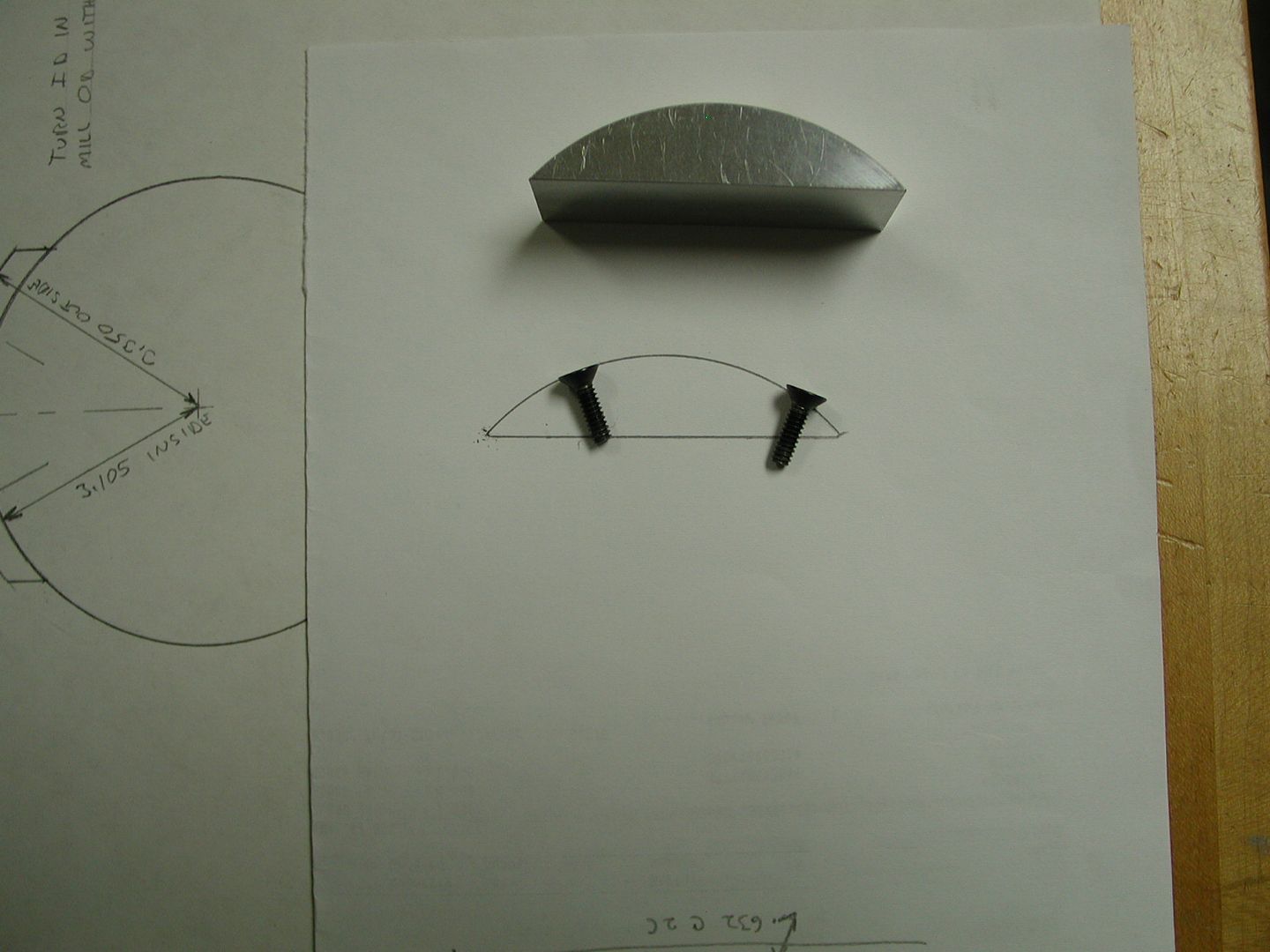
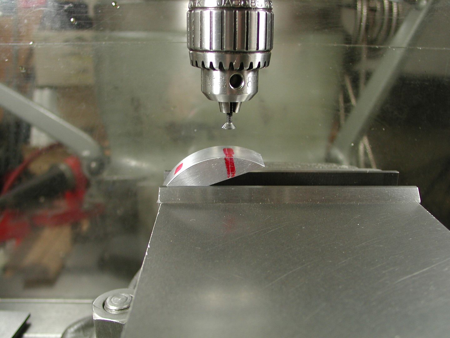
How Would You Figure Out This Angle ????
Collapse
X
-
In the setup shown, you could put a dial test indicator in the drill chuck and angle the part to where the highest reading on the indicator is on the line. Then the bolt hole and countersink will be perpendicular to that point.
You may want to set the part a little deeper in the vise. I can't see enough information to do a mathematical calculation.Last edited by Toolguy; 09-13-2016, 05:48 PM.Kansas City area
-
-
To do it mathematically, you want to know the radius of the curve, and the lateral distance between the holes. Your top picture has a circular drawing at the left that seems to have this info. Draw a line between the screws in the drawing, and you've got a simple triangle, solve it with trig.
Comment
-
-
It's not really an angle it should just point to the center of the radius . If you have a small center finder (combination square set) just put it on the radius and scratch a line on the face of the part and set it vertical in your vise pick up the line drill and c-sink done.
Comment
-
-
Old time method was to bring the center drill down to the mark where you wanted to drill the hole. Then take the 6" scale you always keep in your apron pocked and lay it flat on the part so it's trapped by the center drill. (Drill not running at this point I should point out!) Now look to see of the scale is parallel with the top of the vise. If not, tilt the part in the vise until the scale is parallel and you know you're pointed straight toward the center of the arc - or the center of the bar stock - or whatever curved surface you need to machine on.
In trade school they taught us that as a quick way to center on stock for milling a keyway..
"People will occasionally stumble over the truth, but most of the time they will pick themselves up and carry on" : Winston Churchill
Comment
-
-
Originally posted by Yondering View PostTo do it mathematically, you want to know the radius of the curve, and the lateral distance between the holes. Your top picture has a circular drawing at the left that seems to have this info. Draw a line between the screws in the drawing, and you've got a simple triangle, solve it with trig.
I know I have to flip the part around to drill the other side. I'm just trying to establish the angle so I can set an angle block under the part for easy set up.
I will center the part in the vise and set it down in there deeper. The picture was for illustrative purposes only and my eyeball method.
JL.................
Comment
-
-
Originally posted by duckman View PostIt's not really an angle it should just point to the center of the radius . If you have a small center finder (combination square set) just put it on the radius and scratch a line on the face of the part and set it vertical in your vise pick up the line drill and c-sink done.
JL...............
Comment
-
-
Originally posted by duckman View PostIt's not really an angle it should just point to the center of the radius . If you have a small center finder (combination square set) just put it on the radius and scratch a line on the face of the part and set it vertical in your vise pick up the line drill and c-sink done.
JL............
Comment
-
-
If you want to use the "Get 'er Done" way,....
Set up like you have pictured (perhaps a little deeper in the vise jaws)
Mount an end mill about the size of your screw head in the spindle, and moving left to right, find the highest point of your part. If you use the cutter correctly, it will cut a neat little flat as it touches the work. it is very easy to eyeball this thin flat with your lay out line. Correct the part position as required to get your line upper most.
Snug up the vise, and with the end mill at the "in and out" position you want to put the c'sink and hole, Drop the cutter .010 and cut a deeper flat moving left to right. You want the flat for starting the drill any way.
At some depth of cut, the generated flat and the end mill will be similar in size, and again, eye ball centering will be a piece of cake. easily within .010"
You might have used an edge finder to locate te in and out position according to the requirements, but the perpendicular to the circumference will come through the above method and careful observation.
The entire process takes less time to do than describe, but try it on a piece of pipe and see how it plays out. i use the method frequently, having been taught the process early in my machining experience.
Comment
-
-
Use a protractor and measure the angle on your drawing. 1/2 of that angle to each side for two holes.
Seriously, there is no magic angle; the hole just has to intersect the center of the part radius.
Mark where you want to start the hole and use the ruler trick to locate perpendicular.
Mike
Comment
-
-
I really can't go just by finding the highest point because each hole has to be located .740 from the end so that's why the angle is important.
I cold make the high point anywhere along the radius depending on the angle.... if that makes sense.
Unless I'm missing something here.
JL.................
Comment
-
-
Using Brian's drawing, you know the radius and with the part cut made you can measure the cord distance. Machinery Handbook has a section on cords so using that formula shown in the book, you are able to calculate the angle of the part. Then mark the location of the center of the screw from each end and measure that cord and calculate the angle
The half angle would be from a perpendicular line at the center of the part. That The second one subtracted from 90 should give you the angle you need to tip the part to get the screw centerline perpendicular to face (radius) and run through the center line. the angle of the head should follow the centerline
Set up with a protractor and then use the ruler trick to verify (or vice versa)
rsal
Comment
-
Comment