cutting gears

Collapse
X
 
  • Filter
  • Time
  • Show
Clear All
new posts
  • flopearedmule
    Junior Member
    • Oct 2015
    • 7

    cutting gears

    Hi,
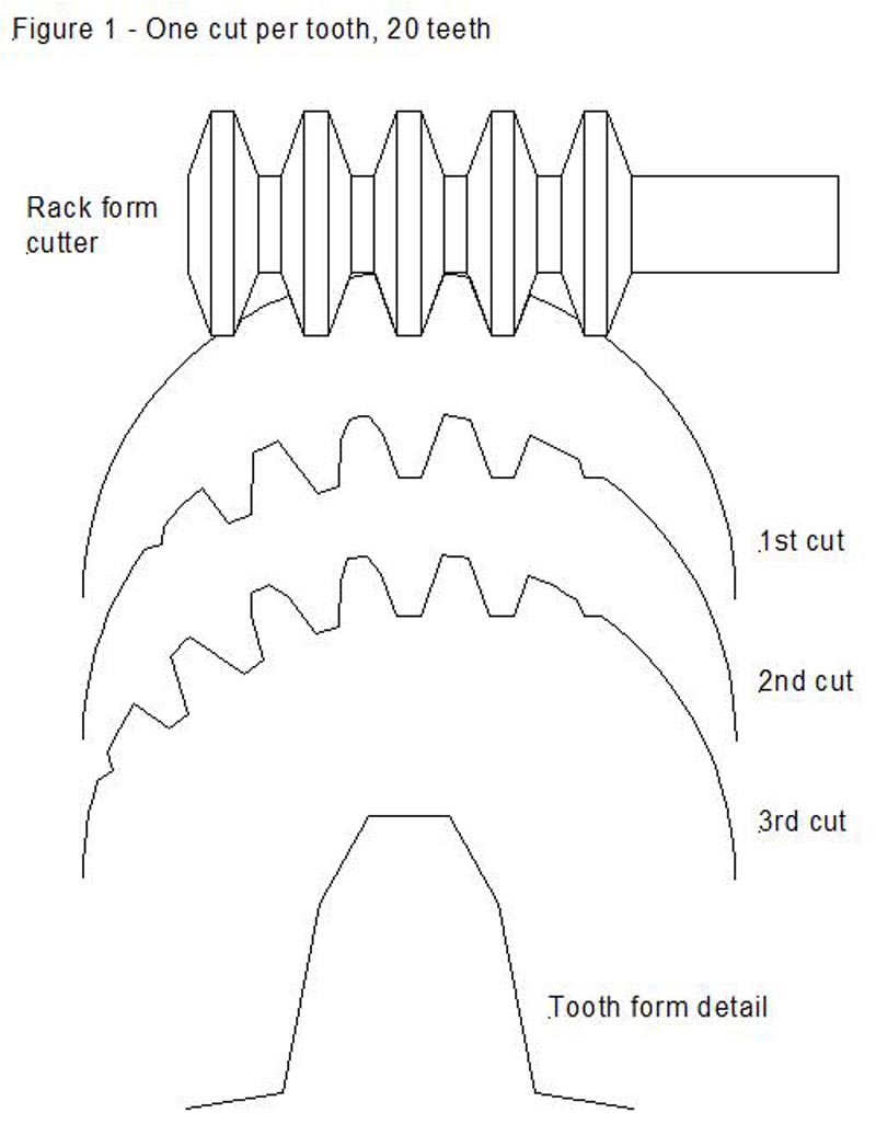
    I have a question about cutting gears with a hob. In strictly IC issue 40 it described it. I was wondering if I had a number 1 cutter that is made to cut 135 teeth to a rack. Would that work to cut a gear of say 50 teeth? For a DP of 8, You could cut all the teeth, then raise your head the circular pitch(.393) distance and cut all the teeth again, then lower the circular pitch(-.393) and cut them one more time. Would that be the same as cutting a gear if I were to make my own straight hob??

    Here is a link to making your own cutter.
    This site gives details of Tony Jeffree's spare time activities in horology and model engineering. There are a number of articles related to the Taig Lathe and Peatol Lathe, the Myford ML&, and the Taig CNC Mill.
    Last edited by flopearedmule; 06-20-2017, 07:46 AM.
  • J Tiers
    Senior Member
    • Jan 2004
    • 44399

    #2
    If you use a rack cutter, such as you describe, then if you move the cutter or gear and rotate the gear, just like mating gears would move, then yes, you could make several passes and essentially "generate" the shape.

    The accuracy would depend on the number of passes and shifts.
    CNC machines only go through the motions.

    Ideas expressed may be mine, or from anyone else in the universe.
    Not responsible for clerical errors. Or those made by lay people either.
    Number formats and units may be chosen at random depending on what day it is.
    I reserve the right to use a number system with any integer base without prior notice.
    Generalizations are understood to be "often" true, but not true in every case.

    Comment

    • Zahnrad Kopf
      Senior Member
      • Apr 2010
      • 563

      #3
      No. It will not work correctly. Form Mills are Form Mills. Hobs are Hobs. And never the two shall meet. An Involute Form Mill is not correctly dimensioned to act as a Hob. It is that simple.

      Comment

      • J Tiers
        Senior Member
        • Jan 2004
        • 44399

        #4
        Originally posted by Zahnrad Kopf View Post
        No. It will not work correctly. Form Mills are Form Mills. Hobs are Hobs. And never the two shall meet. An Involute Form Mill is not correctly dimensioned to act as a Hob. It is that simple.
        I believe that will depend on how close to a rack cutter it is. So it is "not necessarily just that simple".

        A true rack cutter would do as I said.... If it did not, then a hob will not work either. But a hob works. So does a Sunderland machine, which essentially cuts as a series of passes with a section of rack as a cutter, since it is a shaping type machine.

        And, there are different manufacturer modified forms of gear tooth, mostly relating to root etc, but sometimes extending further, which would be incorporated in the hob from that manufacturer.

        The 135 to a rack cutter may not be ideal, not perfect for YOUR purposes, and likely not the best way to cut a 12 tooth pinion (I'd expect the undercut to be wrong, at least)...... But I'd bet that the OP would be perfectly happy with what it cut for most any larger gear. It's not as if the form cutter, used away from (or even AT) it's best tooth count, is going to be a lot better.

        Don't let perfection get in the way of good enough.
        Last edited by J Tiers; 06-20-2017, 12:09 AM.
        CNC machines only go through the motions.

        Ideas expressed may be mine, or from anyone else in the universe.
        Not responsible for clerical errors. Or those made by lay people either.
        Number formats and units may be chosen at random depending on what day it is.
        I reserve the right to use a number system with any integer base without prior notice.
        Generalizations are understood to be "often" true, but not true in every case.

        Comment

        • sansbury
          Senior Member
          • Dec 2008
          • 676

          #5
          What's the intended use of the gears to be made? Depending on how much you care about vibration at speed, noise, backlash, constant velocity, and various other properties, there are plenty of corners you can cut, like making the blank slightly undersized, that will give you gears that turn without binding. For many home shop purposes, that's enough.

          Comment

          • Zahnrad Kopf
            Senior Member
            • Apr 2010
            • 563

            #6
            Originally posted by J Tiers View Post
            I believe that will depend on how close to a rack cutter it is. So it is "not necessarily just that simple".

            A true rack cutter would do as I said.... If it did not, then a hob will not work either. But a hob works. So does a Sunderland machine, which essentially cuts as a series of passes with a section of rack as a cutter, since it is a shaping type machine.

            And, there are different manufacturer modified forms of gear tooth, mostly relating to root etc, but sometimes extending further, which would be incorporated in the hob from that manufacturer.

            The 135 to a rack cutter may not be ideal, not perfect for YOUR purposes, and likely not the best way to cut a 12 tooth pinion (I'd expect the undercut to be wrong, at least)...... But I'd bet that the OP would be perfectly happy with what it cut for most any larger gear. It's not as if the form cutter, used away from (or even AT) it's best tooth count, is going to be a lot better.

            Don't let perfection get in the way of good enough.
            You appear to be grasping, here. It actually is that simple. I was responding directly to the OP's specific question. Not equivocating for what-if's, could-be's, and theoreticals. It's an Involute Form Mill. It's not "how close to a rack cutter it is" because it is NOT a Rack cutter. It's an approximation used to cover a range. Period. As such, it is not actually a Rack cutter. Period.

            Additionally, just because many people are lazy about their standards doesn't mean it's proper or even okay to dispense incorrect information. So I'll refrain from doing so in the same manner I wish others would. Elsewise, just let tiffie or someone else that's never actually done it guide him with misinformation. By the same token, just because someone might be in a home shop environ doesn't mean they necessarily want to be sloppy, either. Involute Form Mills, bastards that they may be, are still made to actual standards. Guess what... ... they are not the same dimensions as Hobs. Not even close. I don't care what kind of Hob you choose. But, I could be wrong. It's not like I design tooling for manufacturing gears and other repeating forms. Oh, wait...

            As far as "perfection" and "good enough", if one's using a Hobbing machine, it's a safe bet they don't desire sh|te for results. I'm willing to be wrong on that, though... I've seen stranger.

            EDIT - Reading this after, one could read it much more sternly than intended. Take it with a grain of salt. I stand by the facts, though.
            Last edited by Zahnrad Kopf; 06-20-2017, 01:55 AM.

            Comment

            • J Tiers
              Senior Member
              • Jan 2004
              • 44399

              #7
              I do agree. Hobbing, shaping etc make correct gears. Form cutters make approximate gears that usually work OK for non-critical uses. Using a near-rack form cutter is not the same as a hob. I supposed that nobody would think it was. Not even the OP.

              Considering the link (you obviously did not follow that) I took it that the OP was COMPARING to a semi-hobbed part (being charitable here), and wondering if he could get somewhat comparable behavior from a single space cutter by taking several cuts (he seems to have specified only 3) while adjusting the gear relative to the cutter in the same way the link suggests. And the answer to THAT is yes, it can be done, and it will generate the form. The more cuts the better the form. And, obviously, the better the rack form of the cutter the better the form of the gear.

              he does not seem to have a hobber, or be hobbing gears, he seems to be trying to do a "nearly-hobbed" gear, without getting a hob or hobbing machine.

              Consequently, it seems appropriate to state that yes, the principle would in fact generate a gear. That gear would mesh with a rack having the same shape teeth as the cutter, obviously. And the more steps that were used, the better the form.

              A near-rack cutter is one possibility, but he referenced making a cutter, so he could make a regular rack form if desired, which is in fact what the link describes. The "135 to a rack" cutter is generally close to the rack form, so it would clearly be the best choice of the usual set, and is easily available without manufacturing a cutter.

              Check the link.... it may horrify you..... but it WILL show why I was not too worried about detailed technical accuracy.
              CNC machines only go through the motions.

              Ideas expressed may be mine, or from anyone else in the universe.
              Not responsible for clerical errors. Or those made by lay people either.
              Number formats and units may be chosen at random depending on what day it is.
              I reserve the right to use a number system with any integer base without prior notice.
              Generalizations are understood to be "often" true, but not true in every case.

              Comment

              • flopearedmule
                Junior Member
                • Oct 2015
                • 7

                #8
                Originally posted by J Tiers View Post
                I do agree. Hobbing, shaping etc make correct gears. Form cutters make approximate gears that usually work OK for non-critical uses. Using a near-rack form cutter is not the same as a hob. I supposed that nobody would think it was. Not even the OP.

                Considering the link (you obviously did not follow that) I took it that the OP was COMPARING to a semi-hobbed part (being charitable here), and wondering if he could get somewhat comparable behavior from a single space cutter by taking several cuts (he seems to have specified only 3) while adjusting the gear relative to the cutter in the same way the link suggests. And the answer to THAT is yes, it can be done, and it will generate the form. The more cuts the better the form. And, obviously, the better the rack form of the cutter the better the form of the gear.

                he does not seem to have a hobber, or be hobbing gears, he seems to be trying to do a "nearly-hobbed" gear, without getting a hob or hobbing machine.

                Consequently, it seems appropriate to state that yes, the principle would in fact generate a gear. That gear would mesh with a rack having the same shape teeth as the cutter, obviously. And the more steps that were used, the better the form.

                A near-rack cutter is one possibility, but he referenced making a cutter, so he could make a regular rack form if desired, which is in fact what the link describes. The "135 to a rack" cutter is generally close to the rack form, so it would clearly be the best choice of the usual set, and is easily available without manufacturing a cutter.

                Check the link.... it may horrify you..... but it WILL show why I was not too worried about detailed technical accuracy.

                That is exactly what I am trying to do. The link I put in the Original Post was how I want to cut the gear(the link was to reference only, so I don't have to try explaining in the post) I could make a rack cutter with only one tooth, I could then cut with one tooth indexing all the way around...then move up the circular pitch of the DP (example a DP of 8, would be .393) and cut all the way around again. Then go down from the centerline the circular pitch(.393 for DP of 8) and cut all the way around again.
                I can buy a no. 1 DP 8 20 pressure angle cutter for $30. I could save the time in making a cutter and heat treating it.

                Comment

                • Zahnrad Kopf
                  Senior Member
                  • Apr 2010
                  • 563

                  #9
                  Originally posted by J Tiers View Post
                  ...<snippage>...

                  Considering the link (you obviously did not follow that) I took it that the OP was COMPARING to a semi-hobbed part (being charitable here), and wondering if he could get somewhat comparable behavior from a single space cutter by taking several cuts (he seems to have specified only 3) while adjusting the gear relative to the cutter in the same way the link suggests. And the answer to THAT is yes, it can be done, and it will generate the form. The more cuts the better the form. And, obviously, the better the rack form of the cutter the better the form of the gear.

                  ...<snippage>...

                  he does not seem to have a hobber, or be hobbing gears, he seems to be trying to do a "nearly-hobbed" gear, without getting a hob or hobbing machine.

                  ...<snippage>...
                  No, no... I am very familiar with the material in the link as well as the concept. It is clear to me now in the light of day that I misread his OP of "...cutting gears with a hob..." and interpreted it incorrectly. My error.

                  Comment

                  • Zahnrad Kopf
                    Senior Member
                    • Apr 2010
                    • 563

                    #10
                    Originally posted by flopearedmule View Post
                    That is exactly what I am trying to do. The link I put in the Original Post was how I want to cut the gear(the link was to reference only, so I don't have to try explaining in the post) I could make a rack cutter with only one tooth, I could then cut with one tooth indexing all the way around...then move up the circular pitch of the DP (example a DP of 8, would be .393) and cut all the way around again. Then go down from the centerline the circular pitch(.393 for DP of 8) and cut all the way around again.
                    I can buy a no. 1 DP 8 20 pressure angle cutter for $30. I could save the time in making a cutter and heat treating it.
                    The concept that you consider can and has been done, but what you are considering does not take the concept nearly far enough. There's a bit more to it. We ( a Gearing Engineer/Designer and myself ) have written software to do this exercise as well as made prototype tooling and had tooling professionally made for the effort. ( ground profiles held to millionths ) It all sounds great until one starts making chips. And then theory laughs at you and it quickly becomes obvious that there are other things to consider.

                    However, for the home shop person not overly concerned with accuracy it will work just fine.

                    Comment

                    • JCHannum
                      Senior Member
                      • Nov 2001
                      • 10091

                      #11
                      All bets are off with import involute gear cutters as their lack of accuracy has been pointed out here previously. The nomenclature for properly made involute cutters describes the best gear form each series will cut to the least acceptable, then a new cutter is made that starts with the next best gear form. A 135 to rack will cut a proper 135 tooth gear and a useable, but approximate rack.

                      Without going through the math involved, the method described will sort of work for many purposes. A possibly better method would entail rotating the blank the requisite amount rather than raising and lowering it.
                      Jim H.

                      Comment

                      • Paul Alciatore
                        Senior Member
                        • May 2002
                        • 17555

                        #12
                        In contradiction to what is stated above, neither a hob nor a form cutter will, in theory, cut a perfect gear.

                        The primary compromise with a form cutter is that it can only be correct for one, specific number of teeth. So, as has been correctly stated above, a #1 form cutter is intended for 135 teeth and up (to a rack). But it can only have the correct form for one of those tooth counts. It is an approximation for all the rest: a pretty good approximation, but an approximation, none the less.

                        But a hob will, in theory, produce correct gear tooth form for all tooth counts. Won't it? Well, not quite. The theory behind a hob is that, as it rotates and as the gear blank also rotates, the teeth of the hob will present themselves in such a manner as to cut each point on the face of the tooth at the proper angle to form an accurate, involute shaped tooth. And this is quite true, in theory. But what it neglects to talk about is that there are not an infinite number of teeth around the circumference of the hob. The teeth on hobs are formed by cutting slots along their length so the hobs will generally have six, eight, or perhaps even more teeth around their circumference. The other thing about hob teeth is that they are based on a rack so each one has a STRAIGHT cutting edge. Rack teeth do have flat faces, you know. So, each tooth on the hob can only cut a FLAT path on the gear. Now at a particular point on the soon-to-be gear tooth, after one of those hob teeth has passed, there is a short delay until the next tooth approaches that point. In that interval the gear blank will have rotated a small amount (if you like the math that angle = 360 / (number of teeth on gear * number of teeth around hob). So now the next STRAIGHT tooth of the hob will cut another FLAT path on a new section of the soon-to-be gear tooth. And those two flats will meet at a helical line across the gear tooth's face. Hence, each gear tooth generated by a hob will consist of a number of helical flats going across it's face.

                        Each of these methods has it's own errors. A form cutter can cut a "perfect" tooth form for one particular tooth count. And it will have a varying amount of error for all others in it's range. A hob will generate a small amount of error for almost ALL tooth counts. This error will be more for smaller tooth counts and less for larger ones. In theory, a hob would cut a perfect rack, but they are never used for that. The primary advantage of a hob is economy as only one hob is needed for all tooth counts.

                        This is probably a large part of the reason why ground gears can be a lot more accurate than those made by either of these methods that employ cutters. Abrasive is distributed with only very small distances from one grain to the next, around the entire circumference of the cutter. So, if the abrasive wheel is dressed properly for the intended tooth count, there will be only very small errors between the time when one grain of abrasive cuts the tooth face and the next.
                        Paul A.
                        s
                        Golden Triangle, SE Texas

                        And if you look REAL close at an analog signal,
                        You will find that it has discrete steps.

                        Comment

                        • Paul Alciatore
                          Senior Member
                          • May 2002
                          • 17555

                          #13
                          As for the OP's original question, he asks if moving a #1 form cutter laterally by one tooth spacing and making another cut will be the equivalent of using the correct form cutter. The simple answer is no. One additional cut is not enough to properly imitate the action of a hob which would make around eight hob tooth passes over each gear tooth. Oh, and those eight cuts are further smoothed out by the slow progress of the hob across the tooth's face as it is fed from one edge of the gear to the other.

                          Anyway, in order to approximate the use of a hob, you would have to make eight or more passes both above and below the centerline pass. That would be a total of 15 passes in all. Of course, the gear blank would have to be rotated by a precise amount for each of these passes. That would be a good approximation of the action of a hob, but the facets generated would follow a straight path, not a helix so the junctions between them would tend to hit a meshing tooth all at once across their length, producing more gear noise.

                          On the practical side, you could reduce the error to any level that you want simply by using a sufficient number of passes. But you would always need to space those additional passes on each side of the centerline of the main cut so it will always be an odd number. Since you are talking about a 50 tooth gear with a #1 cutter, the errors would be less than if you were cutting a 10 tooth gear with that cutter. Depending on the degree of accuracy that you need, perhaps a lesser number of passes could be used. The math needed to find the errors and determine how many passes to make would take a lot longer to do than the gear itself. At least, for me it would. The equation for an involute is not easy to work with.
                          Last edited by Paul Alciatore; 06-20-2017, 12:56 PM.
                          Paul A.
                          s
                          Golden Triangle, SE Texas

                          And if you look REAL close at an analog signal,
                          You will find that it has discrete steps.

                          Comment

                          • J Tiers
                            Senior Member
                            • Jan 2004
                            • 44399

                            #14
                            "Goodness" of the gear depends on how many cuts are made. ONE added cut DOES approximate the shape, very crudely. More shifts and passes will improve it. Hobs make many cuts, which you can see on the hobbed gears, so they are pretty good.

                            Hobbed or otherwise cut gears can be further improved by grinding, or by "crossed axis gear shaving", and other processes which are used for gears that need to be quiet and smooth running, perhaps with very high power transmission.

                            A ground gear is just a gear made with a "cutter" that has a LOT OF small cutting tools all over it, so it makes many cuts at one pass. Otherwise the "cutter" is a similar shape to any other one of the same type.

                            A form cutter CAN be made specifically for a certain gear size and pitch, and it will cut a good gear of proper shape. It's done for big gears, and has been for over a century. These would generally be like end mills, and not like the usual hob or "gear cutter", and made for the specific job.

                            I very much doubt if the OP is interested in these refinements.....

                            In his place, I would buy or make (look it up in the magazine articles or search here)* a form type gear cutter, and use that. It will be WAY better than the link method unless many passes are used, and will be lots faster. You will end up with a very usable gear if done with reasonable care.

                            * There was recently an article on making gear cutters, using the "button method", and it has been explained here as well. I think the Ivan Law book has it as well.
                            CNC machines only go through the motions.

                            Ideas expressed may be mine, or from anyone else in the universe.
                            Not responsible for clerical errors. Or those made by lay people either.
                            Number formats and units may be chosen at random depending on what day it is.
                            I reserve the right to use a number system with any integer base without prior notice.
                            Generalizations are understood to be "often" true, but not true in every case.

                            Comment

                            • flopearedmule
                              Junior Member
                              • Oct 2015
                              • 7

                              #15
                              OK guys, I think I found a solution. By the way, I'm only making a sausage stuffer for our deer meat...I don't have to be perfect, but I want it to turn smooth.
                              I found a place that sells a one row rack cutter(they call it a rack & worm cutter)
                              has a .091" tip and the guy told me it will cut a rack. .091 was the tip dimension I had calculated out if I were to make a cutter.

                              Not sure how to post pictures, or I have a few of my cad drawings and the cutter I'm buying. Here is a link to the cutter, picture in the top right corner.

                              Comment

                              Working...
                              X