Building your own machines

Collapse
X
 
  • Filter
  • Time
  • Show
Clear All
new posts
  • darryl
    Senior Member
    • Jan 2003
    • 14433

    Building your own machines

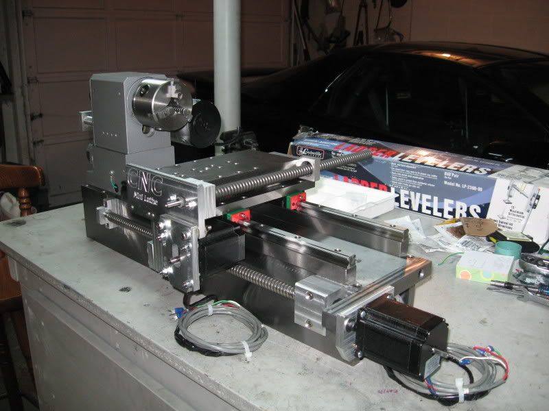
    Some of us have been afflicted with the desire or need to build our own lathe, mill, drill press- what have you. At every stage of any such project, obstacles come up that must be overcome if the finished machine is to meet design goals and perform as intended. There may be nearly as many ways to meet these goals as there are people willing to rise to this challenge. If you are one of these people, you would most likely be interested to see what others have come up with, what issues they faced along the way, how they resolved those issues, and possibly how the design changed during the course of the project.

    Feel free to contribute your own experiences in any such endeavor, whether it be a simple project or a complex one. I humbly suggest we try to keep this thread to thngs which are motor operated, and intended to be able to machine something- the material it works with being irrelevant. A home built dremel type tool qualifies, as would a battery operated pocket drill bit sharpener, as would a scrap metal sorting contraption, as would of course a lathe, mill, drill press, credit card muncher, or an automatic soup stirrer.

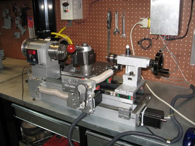
    I would also suggest that any self-functional addition to an existing machine would qualify, like say a homemade toolpost grinder, or a thread grinding attachment. If you've made a left hand screw maker, let's hear what screwed up during that project, and how you unscrewed it.

    Post pictures, add comments or suggestions, where you found a certain component, etc. Since we are all human, a certain amount of 'shop language' can be tolerated, within the rules of the forum of course. We all get frustrated when something doesn't go right- words like !@#$Q#!, or &*#@(*$*@ or @@#m, or crap are ok by me, even some others. That can be, ah, descriptive as part of a project, and it's sometimes good to know what particular process has been enough to drive a person over the edge.

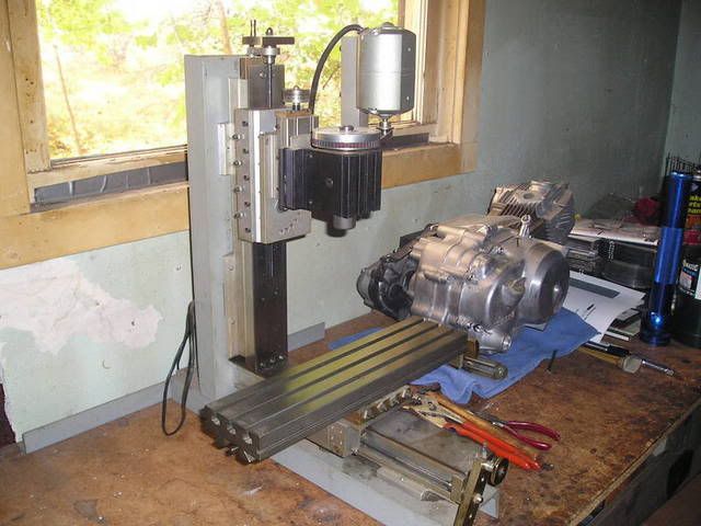
    Without further ado, let me begin by telling of an issue that came up for me tonight, and how I plan to resolve it- unless someone has a better idea-
    I seldom do anything within the scope of logical reason and calculated cost/benefit, etc- I'm following my passion-
  • darryl
    Senior Member
    • Jan 2003
    • 14433

    #2
    Ok, well first off many of you would know that I'm in the planning/construction phase of a combination lathe/milling machine. I elected to start with an existing wood lathe for the bed, instead of round rod ways, support castings for that, etc.

    So far the wood lathe has turned out to be a decent donor. The top of the ways are as flat as I can easily measure, and there's plenty of cast iron to keep things rigid. Earlier tonight I discovered, not surprisingly, that the gap between the ways is not perfectly straight. Mild #$@# here. 
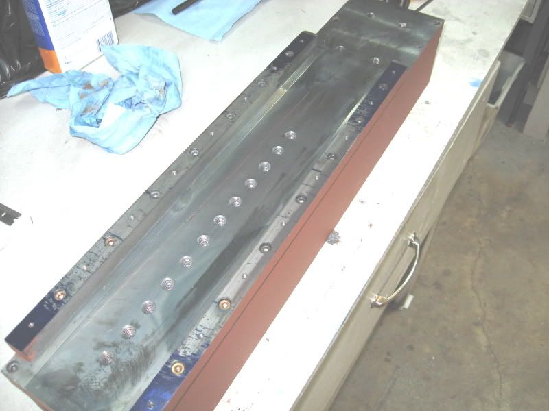
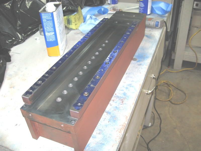
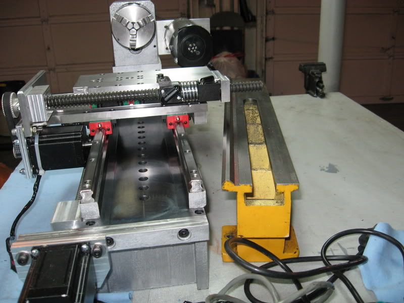
Pretty close, but from rolling a piece of tgp rod against those surfaces, I see a 'hill' of about 3 to 5 thou on one side, and a valley of the same size opposite that. I rolled the rod against those surfaces to take into account any bend that might be in the rod. There was some bend, and 90 degrees to that in either direction, the rod was straight.

    What I plan to try is to set up a straight edge and actually use my router to skim the surfaces of the gap. I'll slow the router way down and take it very easy. I have yet to choose the cutter I'll use, but from the milling work I just did on the x-y table it seems that little pressure will be required, and I will further smooth the surfaces afterwards anyway. My feeling is that the sucess of this will depend largely on the cutter I use, and I'll be paying very close attention to where the cuttings are going. More later.
    Last edited by darryl; 10-06-2008, 04:59 AM.
    I seldom do anything within the scope of logical reason and calculated cost/benefit, etc- I'm following my passion-

    Comment

    • A.K. Boomer
      Senior Member
      • May 2006
      • 20913

      #3
      Iv wondered about building a little lathe with my mill, After seeing Evans mill design I wonder if you could make a short bed lathe with round linear slides instead of bedways, maybe really large ones and three of them? Then just two for the Y or go standard dove.
      It would be interesting...

      Comment

      • J Tiers
        Senior Member
        • Jan 2004
        • 44399

        #4
        Originally posted by A.K. Boomer
        Iv wondered about building a little lathe with my mill, After seeing Evans mill design I wonder if you could make a short bed lathe with round linear slides instead of bedways, maybe really large ones and three of them? Then just two for the Y or go standard dove.
        It would be interesting...
        Aren't you essentially describing an upgraded Unimat?
        CNC machines only go through the motions.

        Ideas expressed may be mine, or from anyone else in the universe.
        Not responsible for clerical errors. Or those made by lay people either.
        Number formats and units may be chosen at random depending on what day it is.
        I reserve the right to use a number system with any integer base without prior notice.
        Generalizations are understood to be "often" true, but not true in every case.

        Comment

        • topct
          Senior Member
          • Jan 2004
          • 2367

          #5


          I built this machine several years ago. It's mostly Taig lathe parts. Two lathe beds bolted to a welded steel frame. A carriage for X&Y, Z is a piece of their riser block stock, and some 6061 bar stock. It stands about 22 inches high.

          I started it before Taig had a mill on the market and used a piece of their lathe cross slide extrusion for a table. When there mill parts became available, I bought one of their tables and redid the X,Y to make it fit. The head tilts 90 degrees and I have used it for a lathe.

          It was fun putting it together, and it has more than paid for itself.

          I learned quite a bit building the thing. Do not use brass for gibs and bushings. Do not use the wrong thread direction for the axis (unlearning reguired) and a bigger motor is always better.
          Gene

          Comment

          • S_J_H
            Senior Member
            • Mar 2006
            • 1182

            #6
            Darryl, I used a small rotary grinder to help remove material quickly on the risers that my linear rails mounted to on my cnc lathe project. That method along with a surface plate and bluing worked pretty well to quickly remove a lot of material. Had to have a very light touch with the rotary tool!! The surfaces I did this for were not actual ways, just mounting surfaces for the linear rails. So surface finish was not to much of an issue. Just needed them nice and flat.
            Initial bluing showed a big bow-

            After a few hours with the rotary tool and it's getting there -

            The bluing is very heavy in the pics as this was just the roughing out stage of the process.

            I'll post more later about my machine builds.

            Steve

            Comment

            • Evan
              Senior Member
              • May 2003
              • 41977

              #7
              After considerable use both manual via keyboard and full CNC on my mill I have identified the one area of the design that qualifies as the "weakest link".

              It isn't weak by any means but it is one place that would benefit from an increase in rigidity. By running the head down on the table (with a block in place of course) and measuring where the flex occurs I find that the majority of the flex is in the bottom of the columns where they attach to the base. Even though they are heavily reenforced that is the point where the leverage is greatest and so is where the largest deflection occurs. Surprisingly to some perhaps the deflections of the ways are slight. That isn't a surprise to me as they are in close accordance to the pre calculated deflection predicted by a mathematical analysis of the design before construction. I wasn't able to perform an equivalent analysis of the main framework because of the complexity of the support structure.

              I will be designing and installing supports that will essentially triangulate the columns to the base as much as possible using some sort of light weight but rigid truss that clears the table and the work on it. The possibility exists of triangulating it to the rear although that presents a depth problem for where the mill is installed on the bench.

              The amount of flex present isn't an issue except with the heaviest of loads applied. Even then it isn't a real problem but if I can improve it I will. There is no such thing as too much rigidity in a machine tool as long as resonance issues are controlled. One possible solution is to use a dynamic system instead of rigid static supports. This would eliminate concerns with differential linear expansion. A dynamic system could be hydraulic, in effect shock absorbers that resist strongly any change or flex in the very short term but because they are bypassed by a needle valve they will accomodate long term changes and can also be tuned to eliminate chatter.
              Free software for calculating bolt circles and similar: Click Here

              Comment

              • darryl
                Senior Member
                • Jan 2003
                • 14433

                #8
                're-inventing the Unimat'- the ways on that lathe are less than 1/2 inch diameter, and they span about 10 inches. Even though much work may be done with the toolpost closer to the headstock, there's still a lot of flex inherent in this setup. Depending on what you're machining, and the diameter of it, cutting forces could be equivalent to the same work being done on a larger machine. Any increase in the diameter of the ways is going to be an improvement in rigidity. I don't think there's an inherent problem to use round ways, but there are issues with alignment that don't exist with what they call a prismatic bed, where one vee controls the position of the carriage, and the opposing flat way doesn't interfere with that.

                That has been one of my issues in designing a bed using a pair of round ways. The carriage should slide along these with very little play, but also no binding. Getting the rods perfectly parallel and perfectly spaced would seem to be of paramount importance. To that end it seems to me the best way to deal with this is to machine all the components that would either ride the ways, or carry the ways themselves, on the same setup (probably on a mill). The chance to end up with the rod ways skewed somewhat once contained in the mounting brackets seems high.

                The best answer to that pair of problems to my way of thinking is to make a setup on a surface plate and cast any and all parts that would either clamp to the ways or ride them. This could mean casting a filler material into spaces on already machined 'constructional blocks', which would be the headstock, tailstock, carriage, and base pieces. Or it could mean casting the entirety of these pieces using something like granite filled epoxy, possiby with a steel framework in place. A third round rod could be fixtured above the two way rods to precisely define the spindle axis, and bearing bores could be cast into exact alignment with this setup. There was a thread a year or more ago on one of these boards where a lot of this was discussed. I can't find it now.

                Where there is a desire to increase the rigidity of round ways, it can be dealt with by supporting the ways from below on some other suitable structure. It would not be out of line, IMO, to use a piece of heavy channel of suitable dimension, and use a filler material such as jb weld or pc7(my choice) to fill the gaps between this channel and the rods. I'm simplifying this of course, as there would need to be attachment points, the channel would need to be stress free, and the carriage could then not have complete round holes to fit the ways- they'd have to be notched out at the bottom. I'm still inclined to give this method a go at some point in the future. I think it has the potential to yield a very accurate and precise machine.
                I seldom do anything within the scope of logical reason and calculated cost/benefit, etc- I'm following my passion-

                Comment

                • Doc Nickel
                  Senior Member
                  • Mar 2003
                  • 5790

                  #9
                  Originally posted by Evan
                  The amount of flex present isn't an issue except with the heaviest of loads applied. Even then it isn't a real problem but if I can improve it I will.
                  -Isn't the "column" a hollow (more or less) aluminum box? Have you considered that "epoxy cement" idea the guys over at CNCZone have been playing with?

                  It wouldn't add much rigidity, per se, but there'd be some resonance/chatter damping, if I understand the idea properly. It'd probably work better for your setup than the CNC guys who are just pouring the hollow base full...

                  Doc.
                  Doc's Machine. (Probably not what you expect.)

                  Comment

                  • Norman Atkinson

                    #10
                    Building your own machines

                    Covered in
                    Making the Most of the Unimat- Rex Tingey

                    Comment

                    • Evan
                      Senior Member
                      • May 2003
                      • 41977

                      #11
                      Isn't the "column" a hollow (more or less) aluminum box?
                      Not exactly. I avoided that sort of structure because it provides no damping. Instead, all of the structures are built up from multiple pieces that are bolted together. This provides far better damping than would be found in a one piece structure since there is a microscopic scuffing action that takes place when a multi layer part is deflected. The two columns on the mill are built up from a pair of 2 x 3 box sections each with a front plate the full length to help tie them together and to provide damping in the Y as well as the X axis. It looks like this in cross section for each of the two columns:

                      Free software for calculating bolt circles and similar: Click Here

                      Comment

                      • S_J_H
                        Senior Member
                        • Mar 2006
                        • 1182

                        #12
                        Most of my cnc lathe build is covered here-

                        I just built it on the fly. Got some ideas from others and it just all came together,
                        I built the bed first totally from scratch using ground steel stock and then mounted the spindle-


                        Then after staring at it a while I just sort of built a carriage and cross slide setup-


                        Finally it was finished-

                        When I built this machine I wanted it to far exceed just converting a mini lathe to cnc in capabilities. For it's size it has no real weak links I have found.
                        The bed is very stiff and a massive improvement over the bed of a mini lathe-
                        A comparison-
                        I can run this machine for hours and hours and not lose even .0005" tool position. Heavily preloaded dual ballnuts on each axis along with the extreme low friction of the linear rails allows this.
                        The weakest link with this machine is me! I don't have the software or g-code skills yet to take full advantage of it,lol

                        I'm hoping my line boring mill turns out just as well.

                        Steve

                        Comment

                        • darryl
                          Senior Member
                          • Jan 2003
                          • 14433

                          #13
                          I got into a bit of routing on my wood lathe bed today. I'm using a 1/4 inch carbide burr in the router, and had no real problems with chatter or side forces, except for what deflection might have occured in the straight edge when the router was passing the center part of it. I think mainly because of flex in the router base, I could make 5 or more passes at the same setting before the bit stopped removing material. These were light, slow passes, and the machined edge feels very smooth. Now I'm going to make a jig to slide along the gap to check for equal width in the gap. Batteries are charging for the camera as we speak, so some pics later.
                          I seldom do anything within the scope of logical reason and calculated cost/benefit, etc- I'm following my passion-

                          Comment

                          • Teenage_Machinist
                            Senior Member
                            • Jun 2008
                            • 1054

                            #14
                            Check the "a box way Gilman slide" thread. Its a horizontal mill/ boring machine/ variable swing lathe.

                            Comment

                            • A.K. Boomer
                              Senior Member
                              • May 2006
                              • 20913

                              #15
                              Nice work SJ, what a precision looking little unit!

                              I bet she purrs like a kitten

                              Comment

                              Working...
                              X