Stepperhead

Collapse
X
 
  • Filter
  • Time
  • Show
Clear All
new posts
  • jackary
    Senior Member
    • Jun 2006
    • 299

    Stepperhead

    Hi All
    I have started this new thread now that I have found out how to do it
    to avoid overlapping (Hijacking) an existing thread called "Lathe build part 2".
    I apologize for any confusion caused.
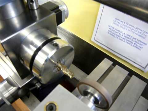
    Over the past few years I have been designing and building a variation
    on the Metalmaster. It is made from solid cast iron blocks and
    standard mild steel sections to avoid making castings. The essential
    difference to the Metalmaster is that the bed remains stationary and
    supported at each end and the head and tailstock can be raised or
    lowered relative to the bed. A secondary vertical column is
    incorporated in the integral tailstock to avoid an unsupported overarm
    and tailstock. The machine uses stepper motors to drive each axis. A
    separate stepper motor is dedicated to driving the headstock for indexing
    the mandrel when required (Stepperhead)
    A 430 watt 3 phase inverter controlled motor is mounted on the lower end of the raising column.
    Using the polyvee pulleys and inverter give speed range of 15 to 3200 rpm.
    The headstock can be moved up or down to change the centre height which can vary between
    80 mm to a max of 220mm for large diameters and allow it to be also be used as a milling machine.
    The axes can be operated either manually, power driven
    by the stepper motors or CNC operated via the lap top computer. I
    entered this machine in the Model Engineers Exhibition in 2008 at
    Ascot UK where it was awarded a Gold Medal and The Bowyer-Lowe Trophy.
    I have written an article which will be printed in the Model Engineers
    Workshop soon. I have added a couple of photos under Stepperhead. I
    have also added some dodgy videos on utube

    Turning a 10 degree taper 1" long at a feed rate of 0.001"/rev using CNC control of X and Z axes

    Diamond wheel moves forwards while end mill is rotated to match the flute spiral, then wheel moves out 0,020" and back to start position while cutter is ind...

    Three flute endmill indexed 120 degreesby stepper motor driven mandrel.Diamond wheel on milling headmoves up to a stop on the lathe bed

    Cutting the teeth of a 15 tooth 32 DPgearwheel using a single point cutter. Indexing the lathe spindle and driving the milling head by CNC stepper motors.

    Milling a tapered spiral flute 5" long. Spindle is rotated 400 degrees and a taper to the 5 " length by moving the cross slide. Milling head winds out and r...

    Wishing a Happy CNC Birthday. I know it lacks the rhythm,tune,and pizazz of the original song, but it means well and always tries to do a good turn


    Regards
    Alan
    Last edited by jackary; 01-12-2009, 11:26 AM.
  • Doc Nickel
    Senior Member
    • Mar 2003
    • 5790

    #2
    That's still amazing. Very nice work.

    Doc.
    Doc's Machine. (Probably not what you expect.)

    Comment

    • dp
      Senior Member
      • Mar 2005
      • 12048

      #3
      How is it realigned after raising/lowering the head and tail stocks? How do you avoid the "round post mill" curse?

      The cross slide details are quite interesting, in particular, the diagonal feed screw.

      Comment


      • #4
        Very nice!! When you made the tailstock, did you bore it out with the headstock in situation?

        Comment

        • jackary
          Senior Member
          • Jun 2006
          • 299

          #5
          Originally posted by dp
          How is it realigned after raising/lowering the head and tail stocks? How do you avoid the "round post mill" curse?

          The cross slide details are quite interesting, in particular, the diagonal feed screw.
          The main column has a triangular gib strip as in the original Metalmaster (see yahoo groups "Metalmaster") The horizontal overarm has a secondary vertical column built in the tailstock. These two vertical columns and the overarm can all be locked together and add up to stiffen and align the whole assembly. The diagonal feed screw rotates a central wormwheel to move the cross slide the full cross slide length.
          Regards
          Alan

          Comment

          • jackary
            Senior Member
            • Jun 2006
            • 299

            #6
            Originally posted by BillH
            Very nice!! When you made the tailstock, did you bore it out with the headstock in situation?
            The tailstock barrel is a close fit into the mandrel bore. The long tailstock barrel was inserted in the mandrel and tailstock sleeve to align the finished components, then the whole assembly was Loctited together. This was the only way I could think of to get it all aligned.
            Regards
            Alan

            Comment

            • Evan
              Senior Member
              • May 2003
              • 41977

              #7
              I have started this new thread now that I have found out how to do it
              to avoid overlapping (Hijacking) an existing thread called "Lathe build part 2".
              I apologize for any confusion caused.
              Thank you Alan. I meant what I said when you first posted it. That is a beauty of a machine. My issues were mainly with John for reasons that go back a while. I in turn apologize to you for any upset this recent nonsense may have caused you.

              What size of steppers have you used, particularly on the spindle? Also, what drivers?
              Free software for calculating bolt circles and similar: Click Here

              Comment

              • jackary
                Senior Member
                • Jun 2006
                • 299

                #8
                Originally posted by Evan
                Thank you Alan. I meant what I said when you first posted it. That is a beauty of a machine. My issues were mainly with John for reasons that go back a while. I in turn apologize to you for any upset this recent nonsense may have caused you.

                What size of steppers have you used, particularly on the spindle? Also, what drivers?
                Evan
                No apology needed. I have used Nema size 23 stepper motors, 56mm long on the cross slide and headstock and 76mm long on the saddle drive the motors , drivers and power supply are all from Motion Control. They seem to supply adequate power. I have set them so that they will stall if the axes are overloaded.
                They are all geared down about 1:10 by worm drives so they are not as fast as production CNC machines but fast enough for me.
                Regards
                Alan

                Comment

                • Evan
                  Senior Member
                  • May 2003
                  • 41977

                  #9
                  Sorry, but by size I meant the holding torque rating.
                  Free software for calculating bolt circles and similar: Click Here

                  Comment

                  • Rigger
                    Member
                    • Jan 2006
                    • 76

                    #10
                    Alan,
                    That machine is amazing, in the time I have been on this forum I have never seen anything that looks so purposeful.
                    Building a machine is one thing but building one to look as well designed as this is another.

                    Short of Steve's CNC lathe which is also a work of art this has to be the best home build presented here.

                    I struggle to make bike fittings look as they should, that you won a Gold medal and a trophy speaks for itself.

                    After the initial misunderstanding I hope you stay around to put a fresh perspective on posts and views.
                    Contrary to what Evan thinks others are willing to accept alternative views.

                    Rigger.

                    Comment

                    • jackary
                      Senior Member
                      • Jun 2006
                      • 299

                      #11
                      Originally posted by Evan
                      Sorry, but by size I meant the holding torque rating.

                      FL57STH56-3008B Holding torque 1.24 NM

                      FL57STH76-2808B Holding torque1.85NM

                      MSD542 Microstepping Driver (4.2A Peak)

                      All by Motion Controls

                      Regards
                      Alan

                      Comment

                      • Peter.
                        Senior Member
                        • Mar 2008
                        • 2982

                        #12
                        Superb piece of engineering Alan hopefully one day I'll get to see it in the flesh too.
                        Peter - novice home machinist, modern motorcycle enthusiast.

                        Denford Viceroy 280 Synchro (11 x 24)
                        Herbert 0V adapted to R8 by 'Sir John'.
                        Monarch 10EE 1942

                        Comment

                        • lazlo
                          Senior Member
                          • Jun 2006
                          • 15631

                          #13
                          Originally posted by jackary
                          FL57STH56-3008B Holding torque 1.24 NM

                          FL57STH76-2808B Holding torque1.85NM
                          For the cretins like myself, who think in Imperial units :

                          1.24 Newton Meters = 176 ounce/inches
                          1.85 Newton Meters = 262 ounce/inches

                          Alan, that is a simply gorgeous build! I realized it was inspired by the Metalmaster multimachine when I saw the distinctive horizontal overarm. Does the headstock elevate like a horizontal boring mill?

                          For those who aren't familiar with the quirky but brilliant "Metalmaster" designed by W. D. Urwick, Tony's got a great page on it here:

                          Impetus Metalmaster - multi-function machine Mr. Urwick triangular radial gib


                          There's also a Yahoo group of folks dedicated to making modern variants.

                          Originally posted by DP
                          How do you avoid the "round post mill" curse?
                          Urwick received a patent in 1950 for the Triangular Gib Key -- there's a triangular notch milled into the round column, and a triangular gib key wedges into a positive lock:


                          Last edited by lazlo; 01-11-2009, 01:39 PM.
                          "Twenty years from now you will be more disappointed by the things that you didn't do than by the ones you did."

                          Comment

                          • jackary
                            Senior Member
                            • Jun 2006
                            • 299

                            #14
                            Does the headstock elevate like a horizontal boring mill?

                            Yes the head ,overarm and tailstock can move up or down relative to the bed
                            Regards
                            Alan

                            Comment

                            • Spin Doctor
                              Senior Member
                              • Nov 2002
                              • 2791

                              #15
                              Very nice piece of work Alan. It certainly looks far more useful than a 3-in-1 combination machine. I wonder just how rigid is the bar bed for the tailstock and what size are the bars. By the way the Flickr link isn't working.
                              Last edited by Spin Doctor; 01-11-2009, 05:05 PM.
                              Forty plus years and I still have ten toes, ten fingers and both eyes. I must be doing something right.

                              Comment

                              Working...
                              X