Tach generator/KB control PCB question

Collapse
X
 
  • Filter
  • Time
  • Show
Clear All
new posts
  • DICKEYBIRD
    Senior Member
    • Apr 2004
    • 3716

    Tach generator/KB control PCB question

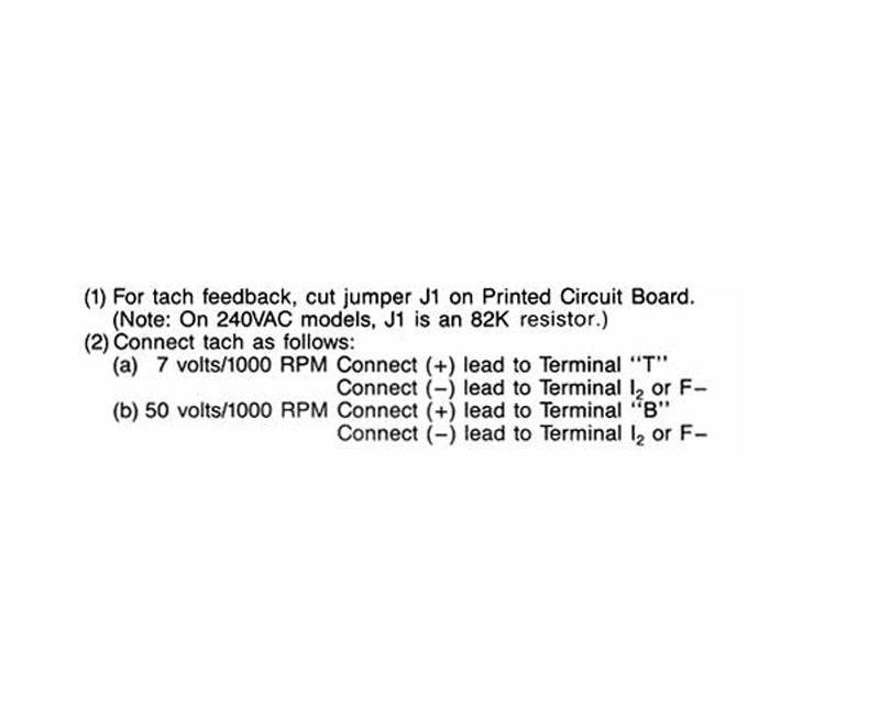
    I recently scored a Servo-Tek 7V/1000 rpm tach generator on ebay and now have it mounted on the rear of the Baldor DC motor on my lathe. I was going to complete the wiring today but am reluctant after a closer look at what’s required. According to the manual for the KBCC-125R speed control, the tach leads connect to 2 terminals on the board and you cut the J1 jumper on the board:


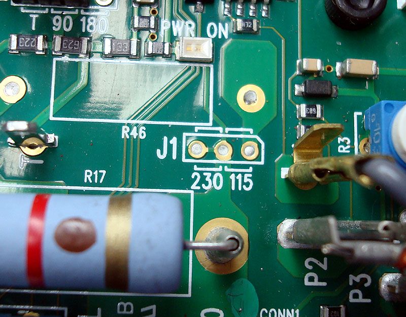
    It looks like they want you to cut through the actual trace on the board at the green spot between the 2 pads on the left of the 3 beside J1. That seems rather final as it’d be real tough (for me anyway) to solder a bridge across those 2 tiny pads if I wanted to revert back to the original setup.
    The speed control works well as-is but I may need better speed regulation with Mach3 threading later on. The manual claims 1% of set speed when using a tach generator.
    If I do cut the trace, what could I use to re-connect the 2 pads if the tach gen thing doesn’t work out? Is there a conductive paint/paste that could be applied cold or maybe a solder paste applied to a tiny piece of copper foil & then quickly flowed with a small iron? The pads are on .100” centers.
    Milton

    "Accuracy is the sum total of your compensating mistakes."

    "The thing I hate about an argument is that it always interrupts a discussion." G. K. Chesterton
  • darryl
    Senior Member
    • Jan 2003
    • 14433

    #2
    Reconnecting the two pads is the simplest thing- just strip some insulation from some wire and pick out a single strand of copper. Tack that across the pads with the soldering pencil and it's done.
    I seldom do anything within the scope of logical reason and calculated cost/benefit, etc- I'm following my passion-

    Comment

    • DICKEYBIRD
      Senior Member
      • Apr 2004
      • 3716

      #3
      Yep, you're right Darryl it does look simple enough. I could practice a bit on an old board first to get my confidence up when/if the time comes.

      I just had another thought. I wonder how difficult it would be to solder on one of those little jumper pin gizmos like hard drives have on them to set master/slave status?
      Milton

      "Accuracy is the sum total of your compensating mistakes."

      "The thing I hate about an argument is that it always interrupts a discussion." G. K. Chesterton

      Comment

      • Don Young
        Senior Member
        • Jun 2004
        • 1163

        #4
        I am pretty sure you have the wrong idea here. There is no 'jumper' on J1 to be cut. The board indicates to 'jumper' the center and right terminals with a short wire or the center and left terminals with a 82K resistor depending on whether the voltage is 115V or 230V. Neither has been installed so there is no need to 'cut the jumper. Just leave that part as it is.
        Don Young

        Comment

        • Mike Nash
          Senior Member
          • Sep 2008
          • 504

          #5
          I wonder if you actually have this newer board http://www.kbelectronics.com/manuals...smt_manual.pdf in your KBCC. The layout sure matches your photo. In which case, J2 will be the one that needs to be set to T rather than J1 being cut. KB's manuals could sure use a refresh on the older units. You also have to watch out for OEM versions which may be a little different than the manuals.

          Comment

          • Paul Alciatore
            Senior Member
            • May 2002
            • 17556

            #6
            There could be some confusion due to board and instruction revisions not being in sync here. I would call the manufacturer about that.

            But, contrary to what Don is saying above, there is a foil jumper between the left and center pad in the photo. A feature like this is fairly common on PCBs when a fairly normal circuit path is etched in the foil pattern but it can be easily cut if another configuration is needed. By placing such a short foil path between two through hole pads, the connection can be easily restored by just placing a wire jumper in the holes and soldering it in place. I recently designed a PCB with just such an arrangement on the ground path where it connected to one of the mounting holes for a screw and standoff. Like the PCB in the above photo, I placed two, apparently unused through hole pads 0.100 inch apart so a wire jumper could be installed if the foil was cut and the connection needed to be restored. It is the best of both worlds: no component or jumper needs to be inserted at initial assembly, but it can be cut and then either jumped or left open as needed.

            The board in the photo above has solder filling the holes in the pads. This should be removed before a wire jumper is inserted. This can be done with a suction type de-soldering tool (solder sucker) or with a product called solder wick or by just heating it until it is melted and inserting an aluminum probe into the hole (or a toothpick or blowing it out). Solder wick is a fine braided wire saturated with soldering flux. It is placed between the hole with solder in it and the soldering iron. When the heat is sufficient to melt the solder, it wicks into the braid and the hole is cleared. My favorite method is the suction tool.

            You could also install a switch to those two pads if frequent changes were anticipated to be needed.

            As for cutting the trace, there are several ways. One, a Dremel tool with a small abrasive wheel will do a very nice job of cutting it. Just do not go through the board or even too deep if it has more than two layers. Two, I frequently use a sharp pocket knife blade as a chisel. I cut from both ends toward the center of the foil jumper with a prying up motion. You can literally peal the copper off the board. Three, a small (1/8" wide) actual chisel is an excellent tool to do it. Like the pocket knife, cut down through the copper at the two ends and then pry it off the board toward the center. Finally, a curved, rat tail file can be used to just file it in half.
            Last edited by Paul Alciatore; 05-12-2013, 11:28 PM.
            Paul A.
            s
            Golden Triangle, SE Texas

            And if you look REAL close at an analog signal,
            You will find that it has discrete steps.

            Comment

            • Barrington
              Senior Member
              • Sep 2008
              • 627

              #7
              Deleted - just noticed Mike Nash's reply covered it.

              Cheers

              .
              Last edited by Barrington; 05-13-2013, 10:52 AM.

              Comment

              • DICKEYBIRD
                Senior Member
                • Apr 2004
                • 3716

                #8
                Wow, many thanks to everyone for the great advice! Not only did I get some good info for future PCB repairs, I got a link to the correct manual for my control. Thank you Mike Nash...you is da' MAN!

                My searches on the KBCC-125R (unit has speed control plus a reversing & dynamic braking module built in) brought up a manual for an older model with a different speed control module. I knew mine had a different looking module but (duhh!) didn't think to search using the KBMM-125 module.

                Turns out the J1 pads are blank & unused on my 110v unit and the tach-gen selection is made at the J2 jumper. No slicing, dicing or splicing needed! Man am I glad I backed away and posted here before screwing up something. You guys are the best!

                Now to figure out for sure if the tach input polarity has to be reversed when the motor direction is reversed. The old manual specifically says you must do it that way; so far I've found no mention of it in the correct manual. Since it is an engineered-for-reversing unit, I'll bet KB made changes to make it a non-issue.
                Milton

                "Accuracy is the sum total of your compensating mistakes."

                "The thing I hate about an argument is that it always interrupts a discussion." G. K. Chesterton

                Comment

                • MaxHeadRoom
                  Senior Member
                  • Apr 2010
                  • 3389

                  #9
                  Once you have the correct tach polarity, the polarity automatically changes on direction change, To get it right first time, the general rule that most drives conform to, is the motor and tach in/out is marked + & - for each, wiring the motor and tach with the same polarity usually insures correct phasing off the bat, the motor usually has RED/BLK leads and the tach has either red blk or +-.
                  Max.

                  Comment

                  • rode2rouen
                    Senior Member
                    • Dec 2008
                    • 465

                    #10
                    You ought to call KB, I found them to be very helpful when setting up one of their units.


                    Rex

                    Comment

                    • MaxHeadRoom
                      Senior Member
                      • Apr 2010
                      • 3389

                      #11
                      I have set up tachs on quite a few of the KB's, all very simple, if you do get the polarity wrong first try, you get motor run-away, so be prepared to stop.
                      Max.

                      Comment

                      • DICKEYBIRD
                        Senior Member
                        • Apr 2004
                        • 3716

                        #12
                        Thanks Max, that's great news. I'd already picked out a DPDT relay to switch polarity and was working on how to operate it from Mach in case it was needed but now I won't have to fiddle with it...sweet!

                        The used tach-gen had no wires attached & the markings weren't + or - but it was easy enough to check with a voltmeter to verify polarity once it was hooked up to the motor & spinning.
                        Milton

                        "Accuracy is the sum total of your compensating mistakes."

                        "The thing I hate about an argument is that it always interrupts a discussion." G. K. Chesterton

                        Comment

                        • MaxHeadRoom
                          Senior Member
                          • Apr 2010
                          • 3389

                          #13
                          If not marked, IIRC, the polarity is detected by tuning the shaft of each in the same direction and observing the generated polarity as the same for each.
                          Max.

                          Comment

                          • DICKEYBIRD
                            Senior Member
                            • Apr 2004
                            • 3716

                            #14
                            Originally posted by MaxHeadRoom View Post
                            Once you have the correct tach polarity, the polarity automatically changes on direction change.
                            I hooked it up last night & tested it in the forward direction only first and can happily report that it works great as far as speed regulation goes. I hooked it up per the new manual; (+) to T, (-) to I2 and moved the J2 jumper up 1 position.

                            Unfortunately, when I reversed motor direction without reversing the tach input, the motor instantly went WFO with no speed control. Fortunately, I was prepared and shut it down instantly with no damage done. I then reversed the tach connections, started the motor in reverse, all was normal with good speed control.

                            So, unless someone has a better solution, I'll have to wire in a DPDT relay to switch the tach input polarity along with spindle direction change. I'm worried about what will happen when the motor is running in reverse (with the relay pulled in) and then shut off. When the relay opens, the spindle will then be coasting down for a bit with the tach input polarity reversed. The drive will be switched off via the inhibit terminal so there's no danger (I think) of motor runaway and hopefully no damage would occur due to the temporary tach input polarity reversal?

                            I suppose I could find a "center off" relay if there is such a thing? Maybe 2 relays or a diode or ??
                            Milton

                            "Accuracy is the sum total of your compensating mistakes."

                            "The thing I hate about an argument is that it always interrupts a discussion." G. K. Chesterton

                            Comment

                            • MaxHeadRoom
                              Senior Member
                              • Apr 2010
                              • 3389

                              #15
                              I assumed you had the 4 quadrant drive, which is automatically reversible for both motor and tach.
                              As long as you inhibit when reversing and do NOT allow the motor to reverse before the tach reversal you should be OK.
                              If you are reversing the armature and do it with two relays, but do not have enough contacts, you could wire a couple of small signal relays in parallel with each reverser, and reverse the tach at the same time as the inhibit occurs.
                              If the inhibit is present, there should be no problem.
                              If you doing everything manually, then just observe the motor at zero before picking up the opposite direction.
                              If your pair of motor reverse'rs are DPDT you can add the braking resistor to stop that much faster.
                              Max.

                              Comment

                              Working...
                              X